Chapter 5 Parameters_VFD-B Series
5-108
Revision 10/2005, BE13, SW V4.08
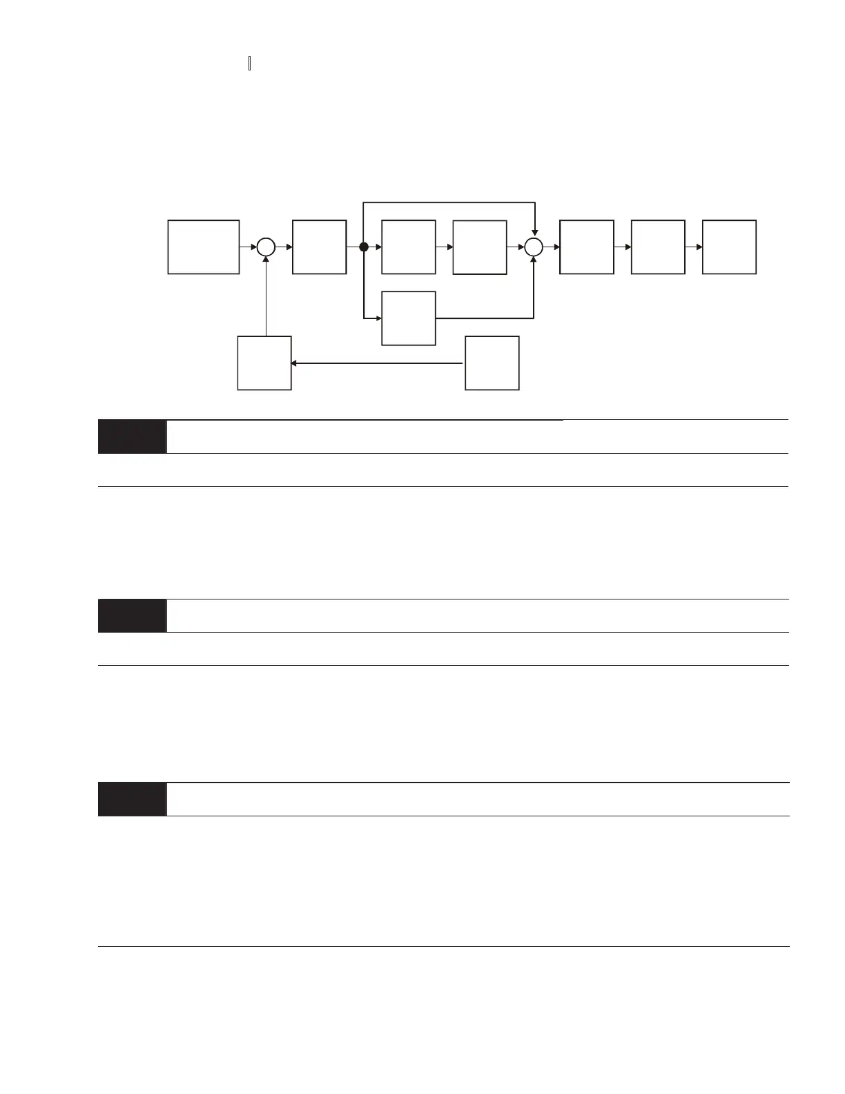
To avoid amplification of measurement noise in the controller output, a derivative digital filter is inserted.
This filter helps to dampen oscillations.
The complete PID diagram is in the following:
P
10-02
I
10-03
D
10-04
10-05
10-01
10-07
10-06
10-00
Setpoint
Input Freq.
Gain
PID
feedback
Integral
gain
limit
Output
Freq.
Limit
Digital
filter
Freq.
Command
10 - 07
PID Output Frequency Limit Unit: 1
Settings 00 to 110 % Factory Setting: 100
This parameter defines the percentage of output frequency limit during the PID control. The formula is
Output Frequency Limit = Maximum Output Frequency (Pr.01-00) X Pr.10-07 %. This parameter will limit
the Maximum Output Frequency. An overall limit for the output frequency can be set in Pr.01-07.
10 - 08
Feedback Signal Detection Time Unit: 0.1
Settings 0.0 to d 3600.0 sec Factory Setting: 60.0
This parameter defines the time during which the PID feedback must be abnormal before a warning (see
Pr.10-09) is given. It also can be modified according to the system feedback signal time.
If this parameter is set to 0.0, the system would not detect any abnormality signal.
10 - 09
aTreatment of the Erroneous Feedback Signals (for PID and PG feedback error)
Factory Setting: 00
Settings 00 Warning and keep operating
01 Warning and RAMP to stop
02 Warning and COAST to stop
 Loading...