Home
Delta
Controller
VFD220B43A
Delta VFD220B43A User Manual
5
of 1
of 1 rating
250 pages
Give review
Manual
Specs
To Next Page
To Next Page
To Previous Page
To Previous Page
Loading...
Chapter 1 Introduction
_
VFD-B Series
1-4
Revision 10/2005, BE13, SW V4.08
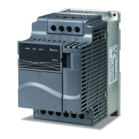
40-100HP/30-75kW (Frame E, E1)
75-100HP/55-75kW (Frame F)
1.3 Prep
aration for Inst
allation and Wiring
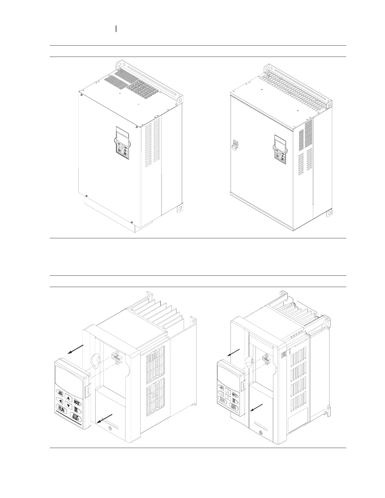
1.3.1 Remove Keypad
1-3HP/0.75-2.2kW (Frame A, A1, A2)
3-5HP/2.2-3.7kW (Frame B)
11
13
Table of Contents
Default Chapter
1
Preface
1
Table of Contents
3
Receiving and Inspection
9
Nameplate Information
9
Model Explanation
9
Chapter 1 Introduction
9
Appearances
10
Series Number Explanation
10
Drive Frames
10
Preparation for Installation and Wiring
12
Remove Keypad
12
Remove Front Cover
14
Lifting
15
Storage
16
Installation and Wiring
19
Ambient Conditions
19
Chapter 2 Installation and Wiring
19
Dimensions
21
General Wiring Information
30
Basic Wiring
31
Wiring for SINK Mode and SOURCE Mode
35
External Wiring
36
2.4.3 Main Terminals Connections
37
Control Circuit Terminals
37
Mains Power Terminals
37
Circuit Diagram for Digital Inputs
39
Control Terminals
39
Grounding Terminals
39
Terminal Symbols and Functions
40
Analog Input Terminals
43
Digital Inputs
43
Digital Outputs
43
General
43
Main Circuit Terminals
45
Preparations before Start-Up
53
Chapter 3 Start up
53
Operation Method
54
Trial Run
54
Description of the Digital Keypad VFD-PU01
57
Chapter 4 Digital Keypad Operation
57
How to Operate the Digital Keypad VFD-PU01
59
Chapter 5 Parameters
61
Summary of Parameter Settings
62
User Parameters
62
Operation Method Parameters
64
Output Function Parameters
67
Input Function Parameters
68
Multi-Step Speed and PLC Parameters
70
Protection Parameters
72
Motor Parameters
74
Special Parameters
74
Communication Parameters
76
PID Control Parameters
76
Fan and Pump Control Parameters
77
Parameter Settings for Applications
78
Speed Search
78
DC Braking before Running
78
Motor Power Switch-Over between AC Motor Drive and Commercial Power
79
Energy Saving
79
Multi-Step Operation
79
Switching Acceleration and Deceleration Times
79
Overheat Warning
80
Two-Wire/Three-Wire
80
Operation Command
80
Frequency Hold
81
Auto Restart after Fault
81
Emergency Stop by DC Braking
81
Over-Torque Setting
81
Skip Frequency Setting
82
Carrier Frequency Setting
82
Keep Running When Frequency Command Is Lost
82
Display the Speed of Load
82
Output Signal in Zero Speed
83
Output Signal at Desired Frequency
83
Output Signal for Base Block
83
Overheat Warning for Heat Sink
83
Description of Parameter Settings
84
Identity Code of the AC Motor Drive
84
Rated Current Display of the AC Motor Drive
84
Parameter Reset
85
Start-Up Display Selection
85
Content of Multi-Function Display
85
User Defined Coefficient K
86
Software Version
87
Password Input
87
Password Set
87
Basic Parameters
90
Maximum Output Frequency
90
Maximum Voltage Frequency
90
Maximum Output Voltage
90
MID-Point Voltage
91
Minimum Output Frequency
91
Minimum Output Voltage
91
Output Frequency Upper Limit
91
Output Frequency Lower Limit
92
Deceleration Time 4
93
Accel/Decel Time Unit
93
Jog Acceleration Time
94
Jog Deceleration Time
94
Jog Frequency
94
Auto-Acceleration / Deceleration
95
Deceleration S-Curve
96
Source of First Master Frequency Command
97
Source of Second Master Frequency Command
97
Source of First Operation Command
98
Source of Second Operation Command
98
Source of the Master Frequency Command
98
Source of the Auxiliary Frequency Command
99
Combination of the Master and Auxiliary Frequency Command
99
Stop Method
99
PWM Carrier Frequency Selections
101
Motor Direction Control
101
2-Wire/ 3-Wire Operation Control Modes
102
Line Start Lockout
103
Loss of ACI Signal (4-20Ma)
105
Up/Down Mode
105
Accel/Decel Rate of Change of UP/DOWN Operation with Constant Speed
106
Keyboard Frequency Command
106
Multi-Function Output Terminals
107
Desired Frequency Attained 1
108
Desired Frequency Attained 2
109
Analog Output Signal
109
Analog Output Gain
110
Digital Output Multiplying Factor
110
Terminal Count Value
110
Preliminary Count Value
111
EF Active When Preliminary Count Value Attained
111
Fan Control
111
Brake Release Frequency
112
Brake Engage Frequency
112
AVI Analog Input Bias
113
AVI Bias Polarity
113
AVI Negative Bias, Reverse Motion Enable/Disable
113
ACI Bias Polarity
113
AUI Analog Input Bias
114
AUI Bias Polarity
114
AUI Input Gain
114
AUI Negative Bias, Reverse Motion Enable/Disable
114
Use of Bias
115
Use of Bias and Gain for Use of Full Range
115
Use of 0-5V Potentiometer Range Via Gain Adjustment
116
Use of Negative Bias in Noisy Environment
116
Gain Adjustment to Use Full Potentiometer
116
Range
116
0-10V Potentiometer Signal to Run Motor in FWD and REV Direction
117
Use Negative Slope
117
AVI/ACI/AUI Analog Input Delay
118
Analog Input Frequency Resolution
118
Multi-Function Input Terminals
118
Accel/Decel Time and Multi-Function Input Terminals
122
Multi-Speed Via External Terminals
123
Digital Terminal Input Debouncing Time
124
Gear Ratio for Simple Index Function
124
Index Angle for Simple Index Function
124
Deceleration Time for Simple Index Function
124
Multi-Step Speeds and PLC Parameters
125
PLC Mode
126
PLC Forward/Reverse Motion
128
Time Unit Settings
130
The Amplitude of Wobble Vibration
131
Wobble Skip Frequency
131
Over-Voltage Stall Prevention
132
Over-Current Stall Prevention During Acceleration
133
Over-Current Stall Prevention During Operation
133
Over-Torque Detection Mode
134
Over-Torque Detection Level
134
Over-Torque Detection Time
135
Electronic Thermal Overload Relay Selection
135
Electronic Thermal Characteristic
135
Fourth Recent Fault Record
136
Under-Current Detection Level
137
Under-Current Detection Mode
137
Under-Current Detection Restart Delay Time
137
User-Defined Low-Voltage Detection Level
137
Motor Rated Current
139
Motor No-Load Current
139
Torque Compensation
139
Slip Compensation
139
Number of Motor Poles
140
Motor Parameters Auto Tuning
140
Motor Line-To-Line Resistance
141
Motor Rated Slip
141
Slip Compensation Limit
141
Torque Compensation Time Constant
141
DC Braking Current Level
143
DC Braking Time During Start-Up
143
DC Braking Time During Stopping
143
Start-Point for DC Braking
143
Momentary Power Loss Operation Selection
144
Maximum Allowable Power Loss Time
144
Baseblock Time for Speed Search
144
Current Limit for Speed Search
145
Auto Reset Time at Restart after Fault
146
Automatic Energy-Saving
147
Automatic Voltage Regulation
147
Software Braking Level
148
Base Block Speed Search
148
B.B. Speed Search with Last Output Frequency Downward Timing Chart
149
B.B. Speed Search with Minimum Output Frequency Upward Timing Chart
149
Speed Search During Start-Up
150
Speed Search Frequency During Start-Up
150
Compensation Coefficient for Motor Instability
150
Communication Address
151
Transmission Speed
151
Transmission Fault Treatment
152
Time-Out Detection
152
Communication Protocol
152
Communication Data Frame
154
Address
154
Function and DATA
155
Check Sum
158
Address List
160
Exception Response
162
Communication Program of PC
163
Response Delay Time
165
PID Control
166
Input Terminal for PID Feedback
166
Gain over the PID Detection Value
166
Proportional Gain
166
Integral Gain
167
Derivative Control
167
Upper Bound for Integral Control
167
Primary Delay Filter Time
167
PID Output Frequency Limit
168
Feedback Signal Detection Time
168
Treatment of the Erroneous Feedback Signals
168
Deviation Range of PID Feedback Signal Error
169
PG Pulse Range
169
PG Input
169
ASR Control
170
Speed Control Output Frequency Limit
170
Sample Time for Refreshing the Content of 210DH and 210EH
170
Speed Control Diagram
171
V/F Curve Selection
172
Start-Up Frequency of the Auxiliary Motor
172
Stop Frequency of the Auxiliary Motor
172
Time Delay before Starting the Auxiliary Motor
173
Time Delay before Stopping the Auxiliary Motor
173
Sleep/Wake up Detection Time
174
Sleep Frequency
174
Wakeup Frequency
174
Common Problems and Solutions
177
Chapter 6 Fault Code Information
177
Reset
181
Chapter 7 Troubleshooting
183
Over Current (OC)
183
Ground Fault
184
Over Voltage
184
Low Voltage (Lv)
185
Overload
186
Over Heat (OH)
186
Display of PU01 Is Abnormal
187
Phase Loss
187
Motor Cannot Run
188
Motor Speed Cannot be Changed
189
Motor Stalls During Acceleration
190
The Motor Does Not Run as Expected
190
Daily Inspection
191
Periodic Inspection
191
Chapter 8 Maintenance and Inspections
191
Periodical Maintenance
192
Appendix A Specifications
197
All Braking Resistors and Braking Units Used in AC Motor Drives
201
Appendix B Accessories
201
B.1.1 Dimensions and Weights for Braking Resistors
203
B.1.2 Specifications for Braking Unit
205
B.1.3 Dimensions for Braking Unit
206
B.2 AMD - EMI Filter Cross Reference
207
Choose Suitable Motor Cable and Precautions
208
General Precaution
208
Saddle on both Ends
209
Saddle on One End
209
The Length of Motor Cable
210
B.2.1 Dimensions
211
B.3 PG Card (for Encoder)
219
PG Card and Pulse Generator
220
PG-02 Terminal Descriptions
222
Terminals
222
Wiring Notes
222
Control Terminals Block Designations
223
Types of Pulse Generators
223
B.3.2 Pg03
224
PG-03 Terminal Descriptions
226
B.4 Remote Controller RC-01
228
B.5 Remote Panel Adapter (RPA 01)
229
AC Input Reactor Recommended Value
230
B.6 AC Reactor
230
B.6.2 AC Output Reactor Recommended Value
231
Connected in Input Circuit
233
Correct Wiring
233
B.6.3 Applications for AC Reactor
233
B.7 Zero Phase Reactor (RF220X00A)
235
B.8 DC Choke Recommended Values
236
B.9 Non-Fuse Circuit Breaker Chart
238
B.10 Fuse Specification Chart
239
Description of the Digital Keypad VFD-PU06
241
Explanation of Display Message
241
B.11 Pu06
241
B.11.3 Operation Flow Chart
242
Appendix C How to Select the Right AC Motor Drive
243
C.1 Capacity Formulas
244
Selection Note
246
Parameter Settings Note
246
C.2 General Precaution
246
How to Choose a Suitable Motor
247
Standard Motor
247
Special Motors
248
Power Transmission Mechanism
248
Motor Torque
249
5
Based on 1 rating
Ask a question
Give review
Questions and Answers:
Need help?
Do you have a question about the Delta VFD220B43A and is the answer not in the manual?
Ask a question
Delta VFD220B43A Specifications
General
Brand
Delta
Model
VFD220B43A
Category
Controller
Language
English
Related product manuals
Delta VFD25AMS43ANSHA
445 pages
Delta VFD25AMS43AFSHA
445 pages
Delta VFD-E
395 pages
Delta VFD-L
16 pages
Delta VFD150B43A
250 pages
Delta VFD022B43B
250 pages
Delta VFD-L Series
88 pages
Delta VFD-V Series
185 pages
Delta VFD-M-D series
163 pages
Delta VFD17AMS23ANSHA
445 pages
Delta VFD9A0MS43ANSHA
445 pages
Delta VFD7A5MS23ANSHA
445 pages
 Loading...