58
ADJUSTMENT
Audio Section
Adjusting Idling Current
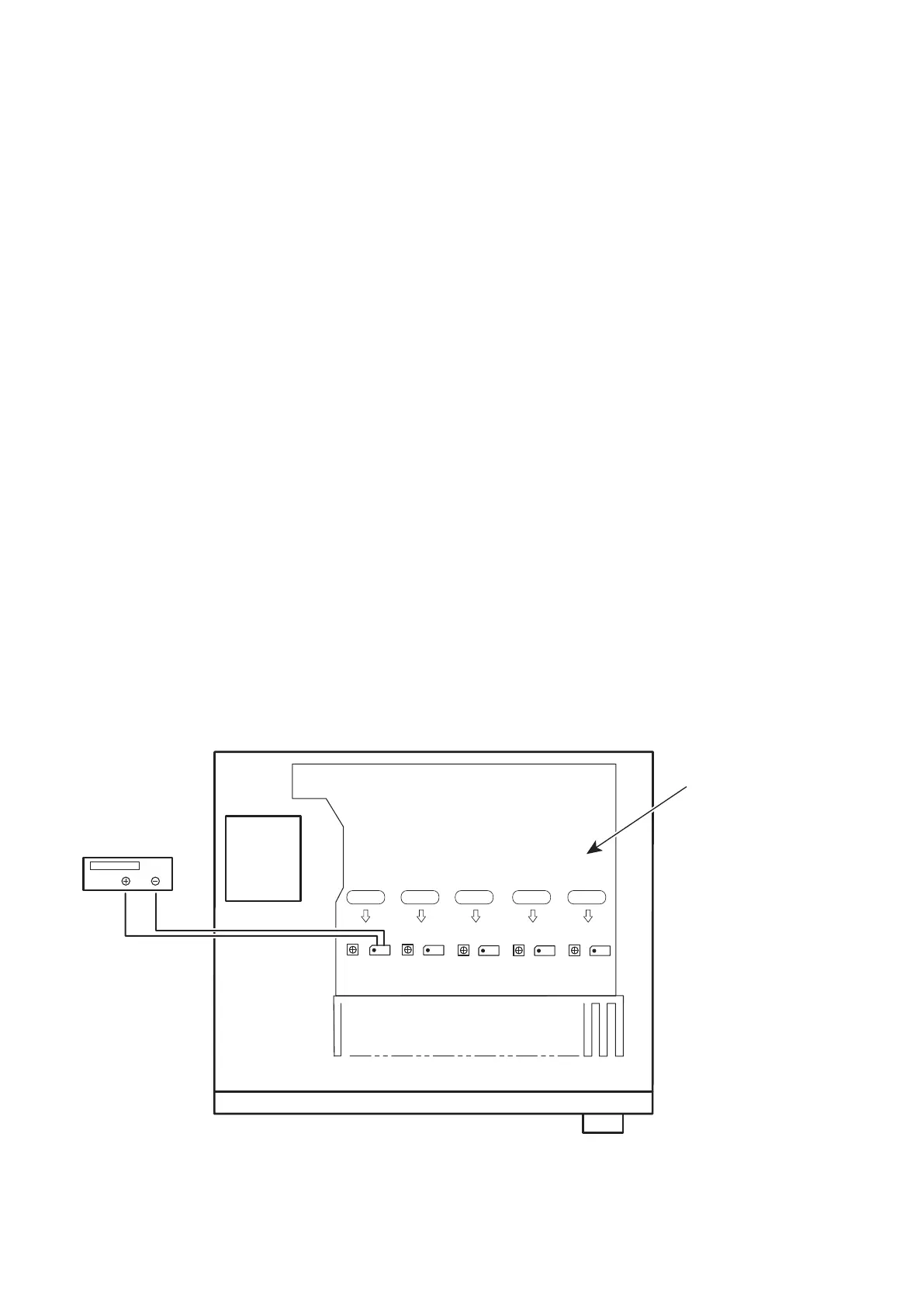
Required measurement equipment: DC Voltmeter
1. Preparation
(1) Avoid direct blow from an air conditioner or an electric fan and humidity should be moderate, and place the set at
normal usage environment.
Temperature should be at 15 °C ~ 30 °C (59 °F ~ 86 °F).
(2) Presetting
• POWER (Power source switch) OFF
• SPEAKER (Speaker terminal) No load
(Do not connect speaker, dummy resistor, etc.)
2. Adjustment
(1) Remove the top cover and set VR510(FL), VR550(FR), VR530(C), VR520(SL), VR540(SR), on MAIN PCB at fully
counterclockwise (
c
) position.
(2) Connect DC Voltmeter to test points (FRONT-Lch: CN510, FRONT-Rch: CN550, CENTER ch: CN530, SURROUND-
Lch: CN520, SURROUND-Rch: CN540).
(3) Connect the power cord to AC Line, and set the power switch to "ON".
(4) Presetting.
MASTER VOLUME :
c
minimum
SPEAKER (Speaker terminal) : No load
(Do not connect speaker, dummy resistor, etc.)
MODE : MCH STEREO
FUNCTION : CBL/SAT
(5) Within 2 minutes after the power on, turn VR510 clockwise (
x
) to adjust the TEST POINT voltage at
1.5mV ± 0.5mV DC.
(6) After 10 minutes from the preset above, turn VR510 to set the voltage to 2.0mV ± 0.5mV DC.
(7) Adjust the Variable Resistors of each channel(VR520-VR550) in the same way.
CN540VR540VR510 CN510 VR520 CN520 VR530 CN530 VR550 CN550
F Lch
S Lch
C ch
S Rch
F Rch
DC Voltmeter
MAIN PCB
 Loading...