EasyManua.ls Logo

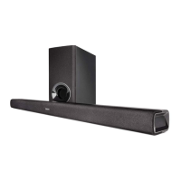
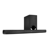
Denon S-302 Service Manual

Denon S-302
155 pages
To Next Page IconTo Next Page
To Previous Page IconTo Previous Page
Page #145 background imageLoading...
Page #145 background image
AUDIO SIGNAL LINE
PROGRESSIVE VIDEO SIGNAL LINE
INTERLACE VIDEO SIGNAL LINE
87654321
A
B
C
D
E
F
SCHEMATIC DIAGRAMS (15/25)
S-302
SIGNAL LINE
SCHEMATIC DIAGRAMS (15/25)
1U-3777-1 DM/XM UNIT (1/2)
ETHER/USB/WiFi BLOCK
w
w
w
.
x
i
a
o
y
u
1
6
3
.
c
o
m
Q
Q
3
7
6
3
1
5
1
5
0
9
9
2
8
9
4
2
9
8
T
E
L
1
3
9
4
2
2
9
6
5
1
3
9
9
2
8
9
4
2
9
8
0
5
1
5
1
3
6
7
3
Q
Q
TEL 13942296513 QQ 376315150 892498299
http://www.xiaoyu163.com

Table of Contents

Other manuals for Denon S-302

Questions and Answers:

Denon S-302 Specifications

General IconGeneral
Audio decoders-
RMS rated power100 W
Audio output channels5.1 channels
Audio formats supportedAAC, MP3, WAV, WMA
Signal-to-Noise Ratio (SNR)92 dB
Satellite speaker frequency range80 - 90000 Hz
Subwoofer typeActive subwoofer
Wireless subwooferNo
FM radioYes
AM band range52 - 1710 kHz
FM band range87.5 - 107.9 MHz
Supported radio bandsAM, FM
Disc loading typeTray
Disc types supportedCD-R, CD-RW, DVD+R, DVD+RW, DVD-R, DVD-RW
Playback disc formatsCD audio, CD video, VCD
Number of optical discs1 discs
Optical disc player typeDVD player
HDMI in0
USB version2.0
Audio (L/R) in3
Composite video in2
Digital audio coaxial in1
AC input voltage120 V
AC input frequency60 Hz
Power consumption (standby)0.3 W
Power consumption (typical)78 W
Product colorBlack
Apple docking compatibilityiPod
Video formats supportedDIVX
Weight and Dimensions IconWeight and Dimensions
Subwoofer weight11200 g
Subwoofer dimensions (WxDxH)212 x 406 x 378 mm
Front speaker dimensions (WxDxH)131 x 76 x 335 mm

Summary

SAFETY PRECAUTIONS

Leakage Current and Laser Safety

Crucial checks for leakage current and laser safety before returning the unit.

Servicing Safety Guidelines

Essential cautions for electric shock, parts handling, and post-service inspection.

ADV-S302 DIMENSIONS

DSW-S302 DIMENSIONS

SC-S302 DIMENSIONS

WIRE ARRANGEMENT

ADV-S302 Wire Arrangement

Detailed steps for correctly routing and securing wires within the ADV-S302 unit.

DSW-302 WIRE ARRANGEMENT

DISASSEMBLY PROCEDURES

ADV-S302 Disassembly Steps

Procedures for removing the side panel and top cover of the ADV-S302 unit.

DRIVE UNIT REMOVAL

Disc Tray Ejection Methods

Steps for drive unit removal based on disc tray ejection status.

FRONT PANEL ASSEMBLY REMOVAL

Front Panel Assy Steps

Detailed instructions for detaching the front panel assembly by removing screws and wires.

REAR PANEL ASSEMBLY REMOVAL

Rear Panel Assy Steps

Instructions for removing the rear panel assembly by unscrewing specific parts.

DSW-S302 DISASSEMBLY

DSW-S302 Rear Panel and Shield Cover Removal

Steps to remove rear panel and shield cover of DSW-S302, with caution.

ATTACHING ANTI-SLIP PADS

Pad Attachment for Speaker Stand and Wall Bracket

Instructions for applying anti-slip pads to speaker stands and wall brackets.

OPTICAL PICKUP DIAGNOSIS AND REPLACEMENT

Laser Drive Current Check

Procedure to diagnose optical pickup failure based on laser drive current values.

LASER PICKUP HANDLING AND REPLACEMENT

Iop Checked Method and Precautions

Method to check laser drive current and safety notes for handling the laser pickup.

LASER CURRENT AND TIME SETTINGS

Laser Current Adjustment and Reset

How to rewrite laser current and reset accumulated laser on time.

TRAVERSE UNIT REPLACEMENT PROCEDURE

Disassembly Steps and Notes

Detailed steps and notes for disassembling the traverse unit, including clamp bracket and tray.

SERVICE MODE OPERATIONS

Aging Mode Procedure

Steps for performing aging mode on the DVD, including preparation and error display.

INITIAL SETTING AND FIRMWARE CHECK MODES

Initial Setting Mode

Procedures for initializing system and DVD data, including standby indicator and display messages.

Microcomputer Firmware Check Mode

Steps to display version information, microprocessor versions, and region codes.

TEST MODE OPERATIONS

Entering and Selecting Test Modes

Procedure to enter and select modes like Laser ON/OFF, Servo adjustment, Trace, and Accumulated time.

TROUBLESHOOTING

ADV-S302 Troubleshooting Guide

Guide for diagnosing and resolving common issues with the ADV-S302 unit.

BLOCK DIAGRAMS

ADV-S302 Block Diagram

System overview diagram illustrating the connectivity and main blocks of the ADV-S302.

SEMICONDUCTOR INFORMATION

ES6178FF Pinout Diagram

Pin configuration diagram for the ES6178FF IC (IC101: 1U-3808).

PARTS LIST NOTES

Parts List Conventions and Warnings

Explains symbols, notations, and warnings for the parts list, emphasizing critical components.

PWB UNIT PARTS LIST

Semiconductor Parts List

List of semiconductors used in PWB units, including part numbers and remarks.

EXPLODED VIEW

DVD Mechanism Exploded View

Visual breakdown of the DVD mechanism unit components for assembly reference.

SCHEMATIC DIAGRAMS

Schematic Diagram Conventions

Explains symbols and notations used in schematic diagrams, including resistance and capacitance values.

1U-3807 FEP Unit Schematics

Detailed circuit diagrams for the 1U-3807 FEP Unit.

Related product manuals