29
Voltage Connection
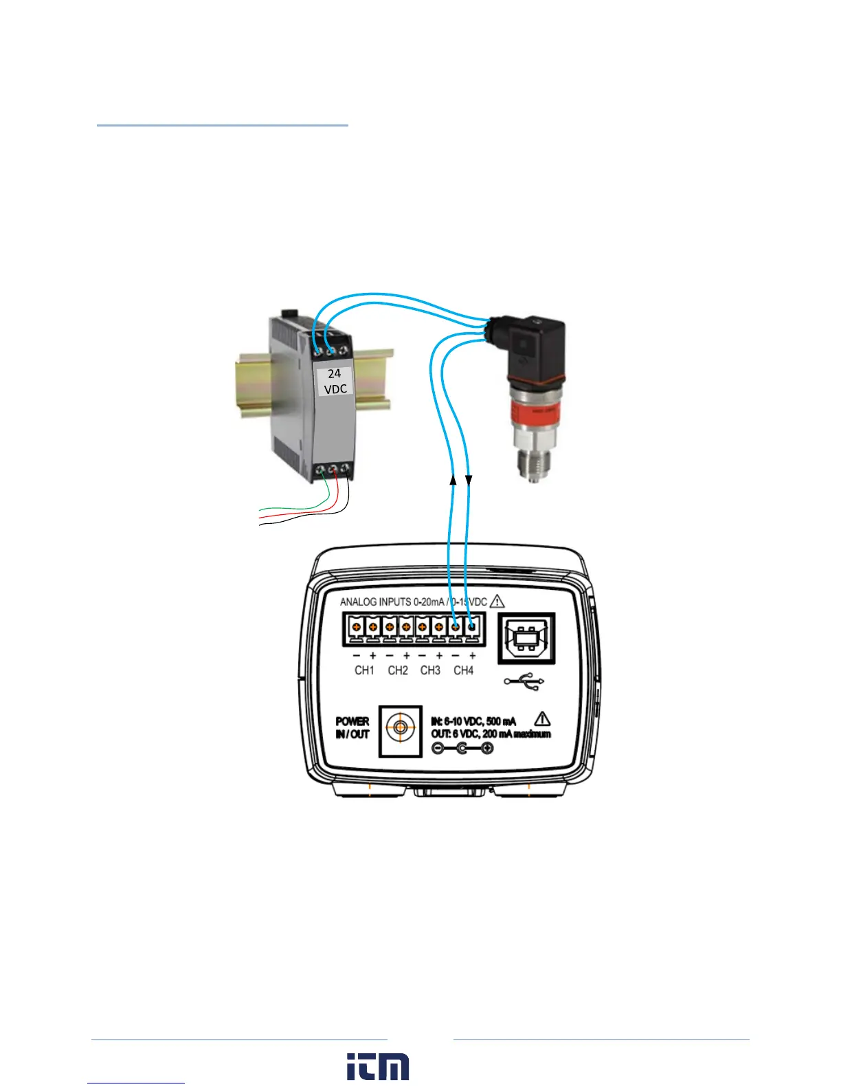
Voltage output sensors and 3-wire current loops will typically use one voltage for powering the sensor
and a second voltage (or current) for sending an output signal. Sometimes the power supply ground and
signal reference conductor is shared between two circuits resulting in a three wire device. This economy
usually comes at the installer’s expense of having to form a junction at the power supply, sensor, or
meter. Sensors having four terminals are also popular and are simply connected to the meter by
observing the indicated polarity between sensor and meter.
L1
L2
G
+
-
Sensor
Power Supply
S
eparately Excited Current or Voltage Loop Configuration
w ww. . com
information@itm.com1.800.561.8187

 Loading...