About the development board Power-Over-Ethernet (PoE) - IEEE802.3af
ConnectCore for i.MX51 Hardware Reference Manual
106
The BCLK signal corresponds to the i.MX51 burst clock signal. This clock signal is not buffered, and its
voltage level is +1.8V. This signal is connected to the peripheral connector through a 0R resister. By
default, this resistor is not populated.
The I2C interface corresponds to i.MX51 I2C port 2. For more information, refer to About the module.
The signal GPIO3_2 can only be used as an input signal to the i.MX51. This signal is intended to be used
as interrupt line in the peripheral boards.
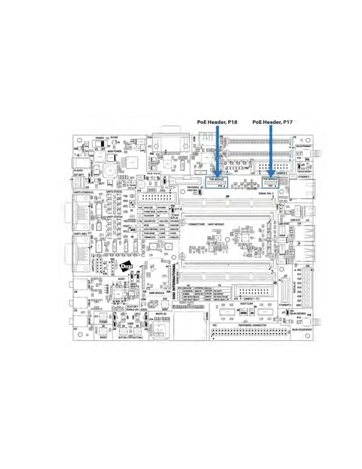
Power-Over-Ethernet (PoE) - IEEE802.3af
The development board provides two PoE module connectors, P17 and P18, to plug a Digi PoE module
(DG-ACC-POE). The PoE module is an optional accessory item that can be plugged on the development
board through the two connectors.
n P17, input connector: provides access to the PoE signals from the Ethernet connector
n P18, output connector: provides the output power supply from the PoE module

 Loading...


