About the module Module pinout
ConnectCore for i.MX51 Hardware Reference Manual
27
Pin I/O Type Signal name Use on module
Use on
development
board
Comments
J1:17
7
GPIO18 EIM_EB2/GPIO2_
22/TRCTL/FEC_
MDIO/SISG2/CSI1_
D2/AUD5_RXFS/CMPOUT1
i.MX51: EIM_EB2 Peripheral
Application
Byte Enable 2
J1:17
8
GPIO18 EIM_WAIT i.MX51: EIM_WAIT Not used
J1:17
9
GPIO18 EIM_EB3/GPIO2_
23/TRCLK/FEC_
RDATA1/SISG3/CSI1_
D3/AUD5_RXC/CMPOUT2
i.MX51: EIM_EB3 Peripheral
Application
Byte Enable 3
J1:18
0
GPIO18 EIM_BCLK i.MX51: EIM_BCLK Peripheral
Application
Clock Burst
By default
not
connected
on
Developmen
t Board.
J2 pinout
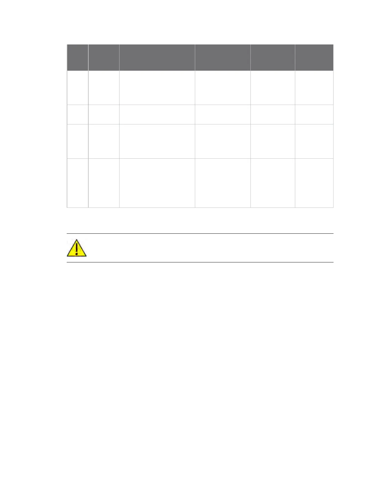
CAUTION! Do not connect signals marked NANDF_* to GND during boot time if you want to
boot from NAND flash.

 Loading...


