About the development board Ethernet 1 interface
ConnectCore for i.MX51 Hardware Reference Manual
81
Pin Signal Voltage Level
6 GPIO3_21/NANDF_CS5# +3.15V
7 GPIO3_22/NANDF_CS6# +3.15V
8 GPIO3_6/DISPB2_SER_DIO/USER_KEY1 +2.775
9 GND 0V
On the development board, GPIO3_6 is connected to USER_KEY1. When using this signal as digital I/O,
the USER_KEY1 should not be used.
Note The digital I/O interface is not protected against ESD, over voltage or inverse polarity. Care must
be taken when using these signals.
WARNING! X45 pins 1, 3, and 4 should not be connected to GND during boot time if you
intend to boot from NAND flash.
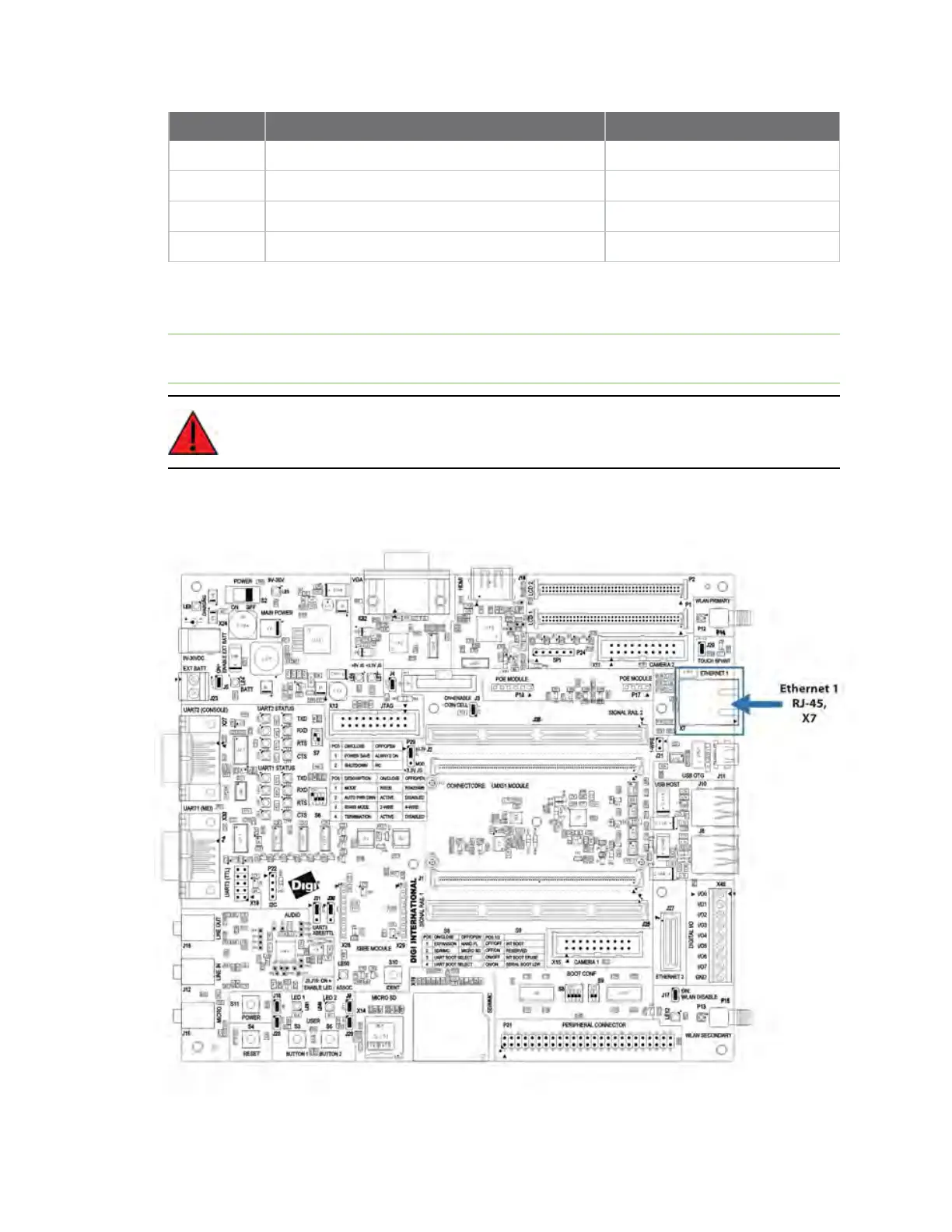
Ethernet 1 interface

 Loading...


