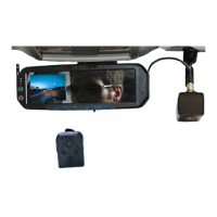
DVM-750 Installation Guide 860-0008-00 Rev C
Digital Ally, Inc |DVM-750 Installation Guide
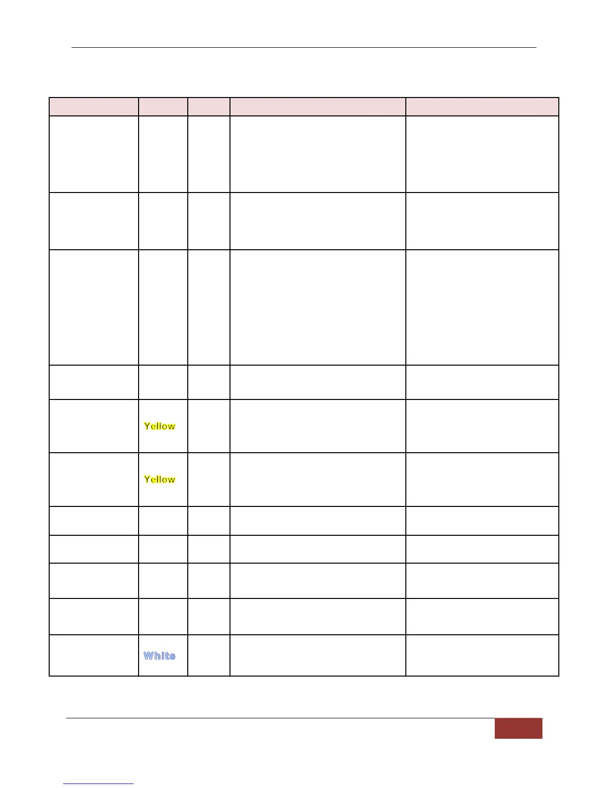
Wiring Connections Chart
REQUIRED. Digital Ally
recommends connecting
directly to the engine
compartment battery. Do NOT
connect to a charge guard or
battery saver system.
REQUIRED. Digital Ally
recommends connecting
directly to the engine
compartment battery
REQUIRED. +12V power only
when ignition is in the ACC or
On position. When ignition is
turned off, the unit can be set to
do a controlled shutdown
automatically based on a user
selectable time setting. This
connection also charges the I/O
box internal battery.
Emergency Light interface. +12VDC
when lights are activated
Connect to light bar controller
Connect directly to one side of siren
speaker. Or, connect one yellow wire
to siren controller if it outputs
+12VDC when siren is ON.
Connect directly to other side of siren
speaker. Or, connect other yellow
wire to ground if the siren controller
outputs +12VDC when siren is ON.
Brake interface. +12VDC signal
when brakes are activated
Connect to brake pedal switch
or 3rd brake light
Vehicle speed sensor for
speedometer interface. (VSS)
Speed sensor that outputs X
number of pulses per mile.
Left turn signal input. +12VDC signal
when turn signal is activated
Right turn signal input. +12VDC
signal when turn signal is activated
Reverse input. Signal grounded
when vehicle goes into reverse
Connect to 0VDC signal when
reverse gear is active (See next
page for details).
 Loading...