DVM-750 Installation Guide 860-0008-00 Rev C
Digital Ally, Inc |DVM-750 Installation Guide
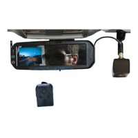
The external Rear Microphone cable should be routed to the rear of the vehicle and is usually
placed covertly on the roofline door seal near the cage. Connect the External Rear Microphone
to the Input labeled “EXT MIC” on the 24” AV Dongle Cable and wrap the connection tightly with
electrical tape.
Rear Microphone AV Dongle Cable
The magnetic GPS antenna/receiver can be placed in the corner on the front or rear dash of the
vehicle, or mounted externally if desired. Use high quality Velcro or double-sided tape if
mounting internally. Connect the GPS antenna cable to the GPS INPUT connector on the back
of the DVM system. Optionally, the antenna/receiver can be mounted on the outside of the
vehicle if better reception is required.
GPS antenna
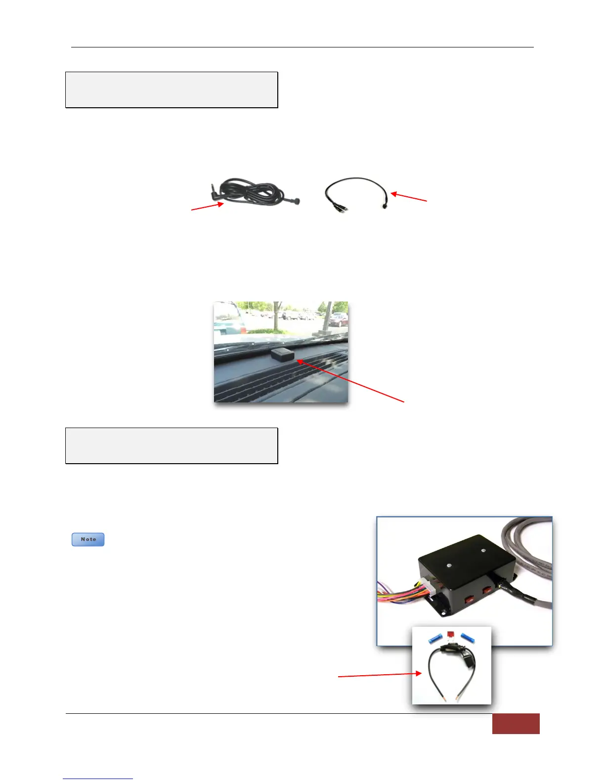
Connect the power and sensor input wiring harness (11-wire, 14-pin, multicolored) to the
interface box and follow the included wiring chart on page 14 to connect the desired optional
inputs and record triggers. Insert the two 7.5 AMP fuses into the slots located on the side of the
interface box, as shown in the picture below.
It is recommended that these connections are made
directly to the police package accessory harness or engine
compartment battery wiring harness for best results. These wires
should be used ONLY for the DVM system and not be tapped
into for installation of any other equipment in the vehicle. Doing
so, could result in possible radio frequency interference from the
other equipment. Do not connect to a charge guard or battery
saver system.
It is highly recommended to install the provided 7.5 Amp fuse
and holder on the Red +12V power source wire. Doing so will
provide the proper protection for the wiring between the source and the
device.
Step 6: GPS and Rear Microphone
Connections
Step 7: Power, Ignition, Ground,
and Trigger Connections
 Loading...