Section 2: Installation
*These units draw current from the Corbus to power devices external to the module. This current must be added to the total
Corbus current. See manufacturer's specifications for the current draw of each device.
** For HSM2955 current draw refer to HSM2955 installation manual.
Line Loss
Voltage loss through wire resistance must be considered for all installations. To ensure proper operation, at least 12.5VDC
must be applied to all modules on the system (when AC is connected and the battery is fully charged). If less than 12.5VDC is
applied, system operation is adversely affected.
To correct the problem, try any or all of the following:
1. Connect a HSM2300/2204 power supply between the alarm controller and the module to provide additional power to the
Corbus.
2. Reduce the length of the Corbus run to the module.
3. Increase the gauge of wire.
Capacitance Limits
An increase in capacitance on the Corbus affects data transmission and causes the system to slow down. Capacitance
increases for every foot of wire added to the Corbus. The capacitance rating of the wire used will determine the maximum
length of the Corbus.
For example, 22-gauge, non-shielded, 4-conductor wire has a typical capacitance rating of 20 picofarads per foot (which is
20nF/1000’). For every 1000' of wire added – regardless of where it is run – the capacitance of the Corbus increases by
20nF.
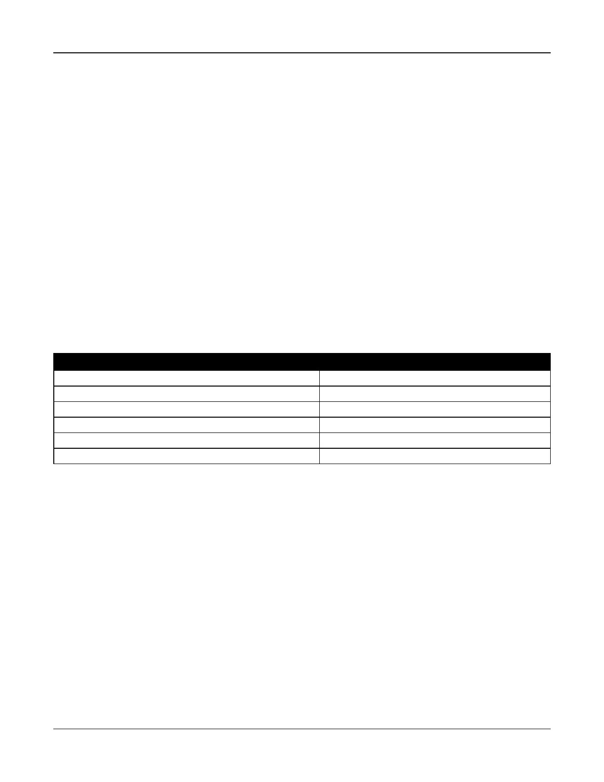
The following table indicates the total wire distance allowed for the capacitance rating of the wire used:
Table 2-3 Wire Capacitance
Wire Capacitance per 1000’ (300m) Total Corbus Wire Length
15nF 5300’/1616m
20nF 4000’/1220m
25nF 3200’/976m
30nF 2666’/810m
35nF 2280’/693m
40nF 2000’/608m
2.4 Installing Modules
Remove all power from the system while connecting modules to the alarm controller.
2.4.1 Zone Expander
The main alarm controller has connection terminals for zones 1 to 8. Additional HSM2108 zone expanders may be added to
increase the number of zones on the system. Each zone expander consists of one group of 8 zones. At enrollment, the zone
expander is automatically assigned to the next available zone slot. Connect the RED, BLK, YEL and GRN terminals to the
Corbus terminals on the alarm panel. Board current draw: 30mA.
- 18 -

 Loading...