Appendix 6: Wiring Diagrams
PGM Wiring
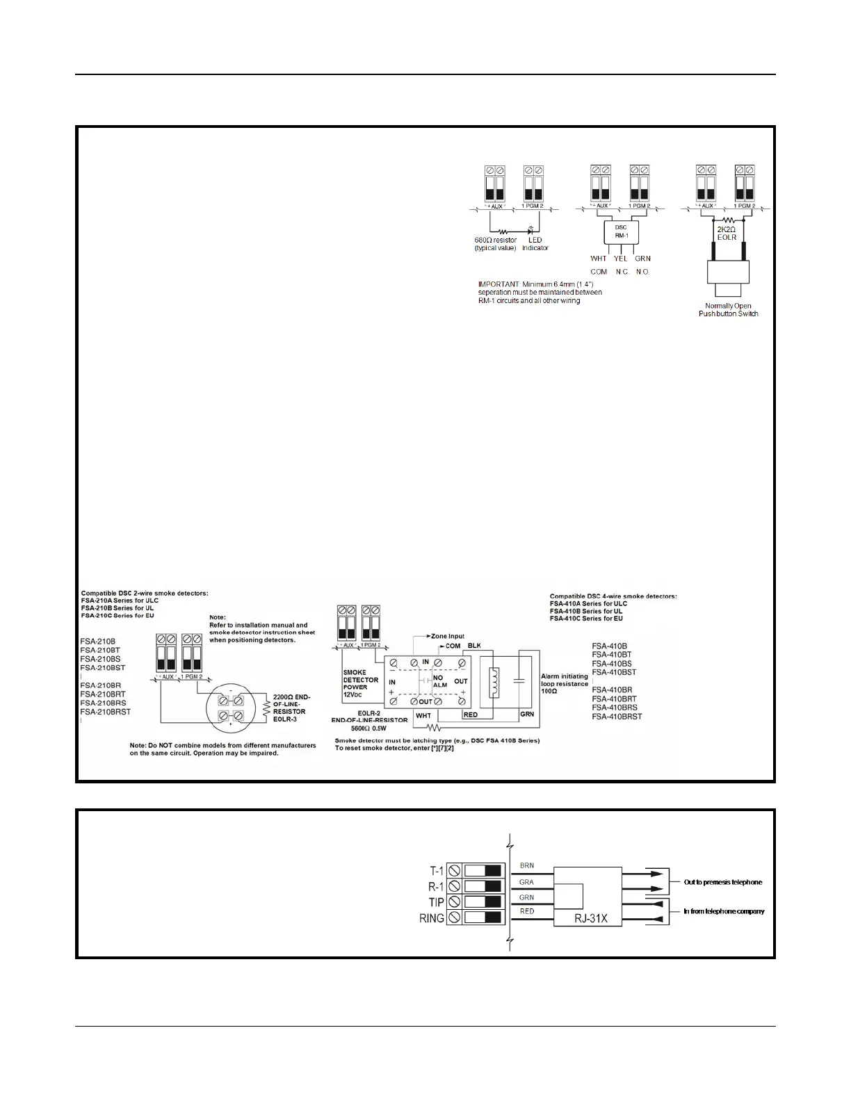
PGMs switch to ground when activated by control panel.
Connect the positive side of the device to be activated to the AUX+
Terminal. Connect the negative terminal to the PGM.
Current output is as follows:
PGM 1, 3, 4 50mA
PGM 2 300mA
For currents levels greater than 300mA a UL listed RM-1 or RM-2
relay module is required.
PGM2 can also be used for 2-wire smoke detectors.
Note: Use SEOL resistors on FIRE ZONES ONLY.
PGM 1, LED Output with current limiting resistor and
Optional Relay driver output
2-wire Smoke Detectors Initiating Circuit
l Style B (Class B), Supervised, Power Limited
l Compatibility Identifier PC18-1
l DC Output Voltage 9.8-13.8 VDC
l Detector Load 2 mA (MAX)
l Single-end-of-line (SEOL) Resistor 2200Ω
l Loop Resistance 24Ω (MAX)
l Standby Impedance 1020Ω (NOM)
l Alarm Impedance 570Ω (MAX)
l Alarm Current 89 mA (MAX)
l Maximum number of 2-wire Smoke Detectors 18
2-wire Smoke Detectors
Compatibility ID For FSA-210 Series is: FS200
4-wire Smoke Detectors
Telephone Line Wiring
Wire the telephone connection terminals (TIP, Ring, T-1, R-
1) to an RJ-31x Connector as indicated.
For connection of multiple devices to the phone line, wire in
the sequence shown.
Telephone format is programmed in section [350].
Telephone Call Directions are programmed in section [311]
- [318].
Note: For ULC installations, please refer to the ULC Installation Information Sheet part#29002157.
- 218 -

 Loading...