Section 2: Installation
2.4.4 Power Supply Wiring
The HSM2300/2204 power supply/high-current output module provides up to 1.0A of additional current and can be used to
add up to four programmable outputs (HSM2204 only) to the alarm system.
The 4-wire Corbus connection provides communication between the module and alarm panel. Connect the RED, BLK, YEL
and GRN terminals to the Corbus terminals on the alarm controller. If O1 is not used, connect to Aux with a 1K resistor. Board
current draw: 1.2A.
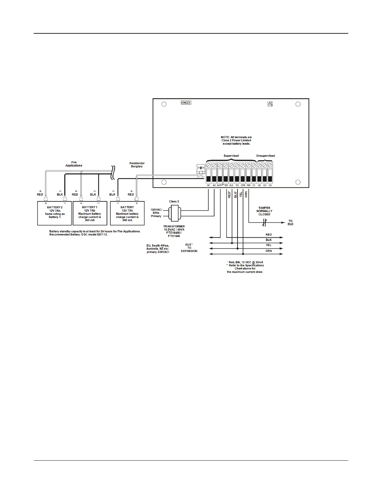
Figure 2-7 Power Supply Wiring
2.4.5 Keypad Wiring
To wire a keypad to the alarm controller, remove the keypad backplate (refer to the keypad installation sheet) and connect
the RED, BLK, YEL and GRN terminals to the corresponding terminals on the alarm controller.
Keypad Zone/PGM Wiring
Hardwired devices can be connected to hardwired keypads with inputs (zone) or outputs (PGM). This saves from running
wires back to the control panel for every device.
To connect a zone device to HS2LCD, HS2ICON, HS2LED and HS2TCHP keypads, run one wire to the P/Z terminal and the
other to B. For powered devices, use red and black to supply power to the device. Run the red wire to the R (positive) ter-
minal and the black wire to the B (negative) terminal.
Keypad zones support Normally Closed Loops, Single End of Line and Double End of Line.
To connect the PGM output, run one wire to the P/Z terminal and the other to R.
- 20 -

 Loading...