Section 2: Installation
UL Compatibility ID For FSA-210B Series is: FS200
Note: For ULC listed installations, use FSA-210A and FSA-410A series.
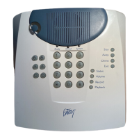
2.4.10 Bell Wiring
These terminals supply 700mA of current at 10.4 - 12.5VDC for commercial/ residential installations. To comply with NFPA
72 Temporal Three Pattern requirements, section [013] Opt [8] must be ON. Note that steady, pulsed alarms are also sup-
ported.
Figure 2-13 Bell Wiring
The Bell output is supervised and power limited by 2A thermistor. If unused, connect a 1000Ω resistor across Bell+ and Bell-
to prevent the panel from displaying a trouble. See "[*][2] Trouble Display" on page 44.
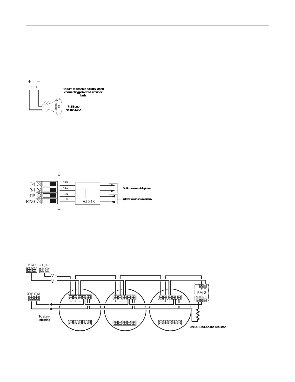
2.4.11 Telephone Line Wiring
Wire the telephone connection terminals (TIP, Ring, T-1, R-1) to an RJ-31x connector as indicated in the following diagram.
For connection of multiple devices to the telephone line, wire in the sequence indicated. Use 26 AWG wire minimum for wir-
ing.
Figure 2-14 Telephone Line Wiring
Note: Ensure that all plugs and jacks meet the dimension, tolerance and metallic plating requirements of 47 C.F.R. Part 68,
Sub-Part F. For proper operation, no other telephone equipment must be connected between the control panel and the tele-
phone company facilities.
2.4.12 Smoke Detector Wiring
All zones defined as Fire must be wired according to the following diagram:
Figure 2-15 Smoke Detector Wiring
- 24 -

 Loading...