Communication
Eaton 9130 700/3000 VA UPS User’s Guide 164201718—Rev 7 www.eaton.com/powerquality 40
l
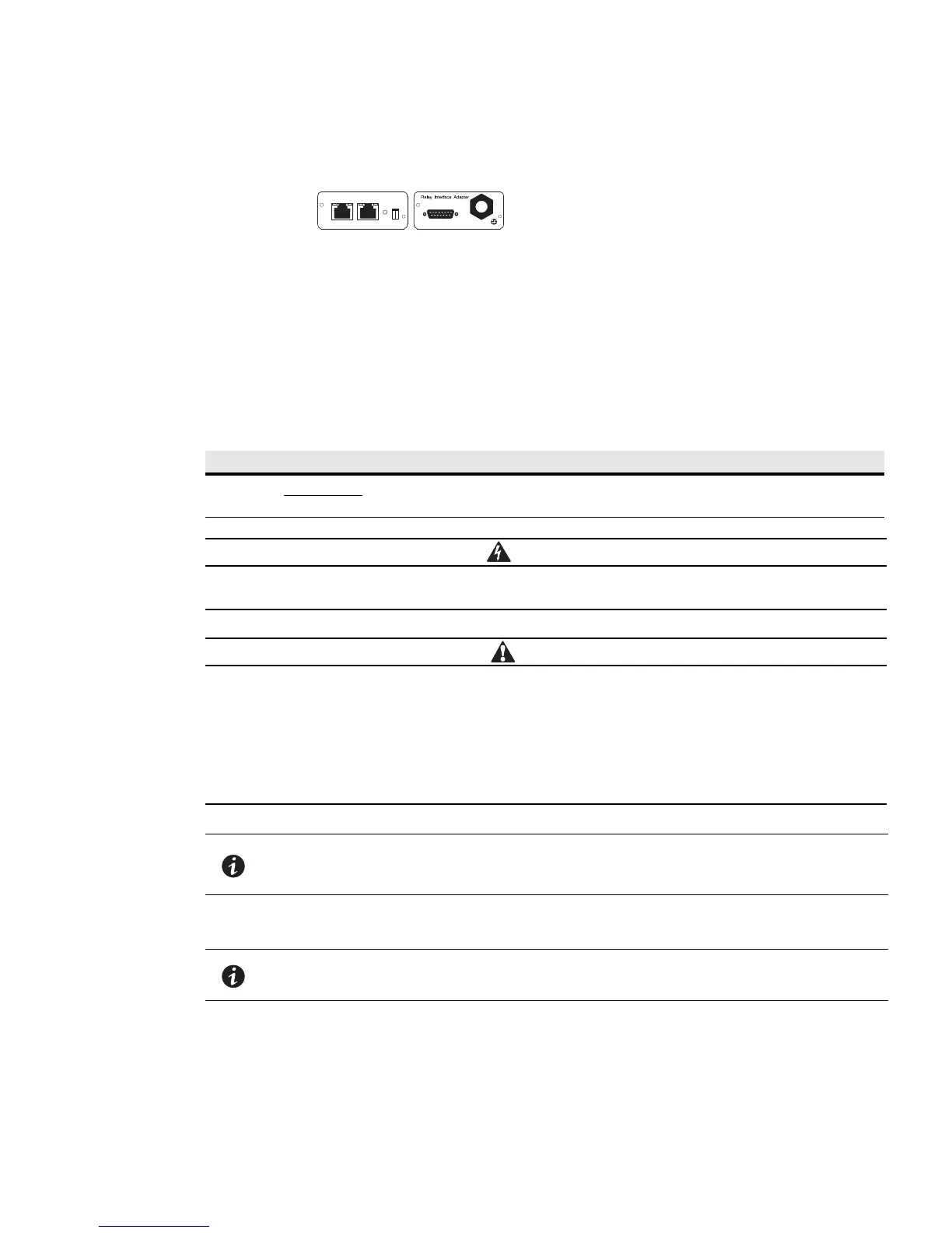
Relay Interface Card - has isolated dry contact (Form-C) relay outputs for UPS status: Utility failure, Low
battery, UPS alarm/OK, or On bypass.
Relay Interface Card
Network Card-MS
Figure 20. Optional Connectivity Cards
See Figure 18 on page 38 for the location of the communication bay.
Remote Emergency Power-off
REPO is used to shut down the UPS from a distance. This feature can be used for shutting down the load and
the UPS by thermal relay, for instance in the event of room overtemperature. When REPO is activated, the UPS
shuts down the output and all its power converters immediately. The UPS remains on to alarm the fault.
Table 7 provides REPO connections.
Table 7.
Wire Function Terminal Wire Size Rating Suggested Wire Size
REPO L1 4
–0.32 mm
2
(12–22 AWG) 0.82 mm
2
(18 AWG)
L2
REPO Connections
The REPO circuit is an IEC 60950 safety extra low voltage (SELV) circuit. This circuit must be
separated from any hazardous voltage circuits by reinforced insulation.
l
The REPO must not be connected to any utility connected circuits. Reinforced insulation to the
utility is required. The REPO switch must have a minimum rating of 24 Vdc and 20 mA and be a
ded
icated latching-type switch not tied into any other circuit. The REPO signal must remain
active for at least 250 ms for proper operation.
l
To ensure the UPS stops supplying power to the load during any mode of operation, the input
power must be disconnected from the UPS when the emergency power-off function is
activated.
NOTE For Europe, the emergency switch requirements are detailed in Harmonized
document HD-384-48 S1, “Electrical Installation of the Buildings, Part 4: Protection
for Safety, Chapter 46: Isolation and Switching.”
NOTE Leave the REPO connector installed in the REPO port on the UPS even if the REPO
function is not needed.
 Loading...