Communication
Eaton 9130 700/3000 VA UPS User’s Guide 164201718—Rev 7 www.eaton.com/powerquality 41
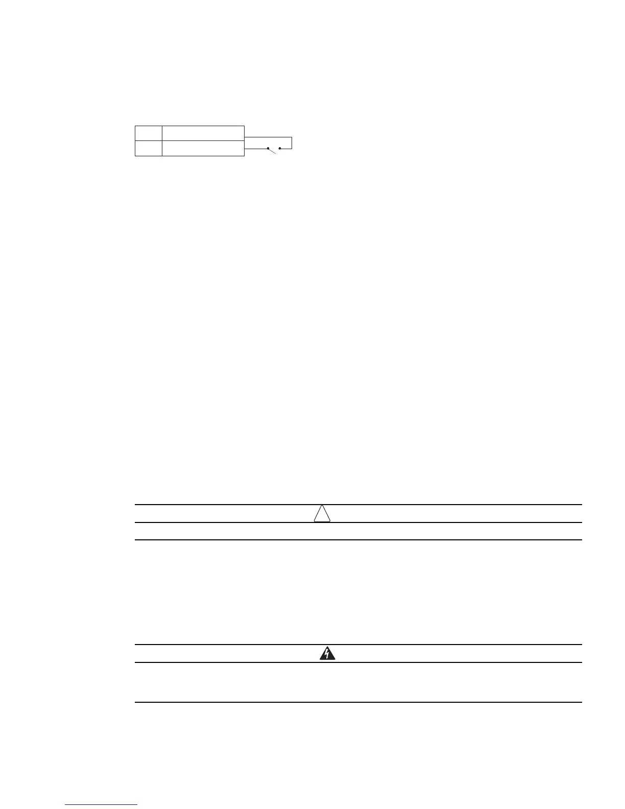
See Figure 18 on page 38 for the REPO location. Figure 21 shows a schematic of the REPO connector
contacts.
– Polarity
2
+ Polarity
1
REPO
Figure 21. REPO Connector Contacts
You can set the REPO polarity. See the “REPO Input Polarity” setting in “User Settings” on page 28.
Depending on user configuration, the pins must be shorted or open to keep the UPS running. To restart the
UPS, reconnect (re-open) the REPO connector pins and turn on the UPS manually. Maximum resistance in the
shorted loop is 10 ohm.
Forced to Bypass State
In the “Force to Bypass” state, the UPS transfers to Bypass model in every condition except frequency
converter and generator mode.
The following models have the REPO port configured f
or “Force to Bypass” function:
Rack Models
l
PW9130G1000R-XL2UAU
l
PW9130G1500R-XL2UAU
l
PW9130G2000R-XL2UAU
l
PW9130G3000R-XL2UAU
Tower M od els
l
PW9130G700T-XLAU
l
PW9130G1000T-XLAU
l
PW9130G1500T-XLAU
l
PW9130G2000T-XLAU
l
PW9130G3000T-XLAU.
Always test the REPO function before applying your critical load to avoid accidental load loss.
Relay Output Contacts
The UPS incorporates three programmable relay outputs with potential free contacts for remote alarm
indications: a standard relay port and two outputs in the RS-232 communication port. See Figure 18 on
page 38 for the locations of the ports. An additional four relay outputs can be obtained with the compatible
Relay Interfa
ce Card.
Configure the relay outputs with the “Relay Configuration” setting in “User Settings” on page 28.
The relay output contacts must not be connected to any utility connected circuits. Reinforced
insulation to the utility is required. The relay output contacts have a maximum rating of 30
Vac/1A
and 60 Vdc/2A nominal values.