Communication
Eaton 9130 700/3000 VA UPS User’s Guide 164201718—Rev 7 www.eaton.com/powerquality 42
Table 8 shows the options for the relay output contacts.
Table 8. Relay Output Configuration Options
Signal Description
UPS ok Activated when the UPS is feeding the lo
ad on inverter or on bypass and no alarms are active
On Bypass Activated when the UPS is NOT on bypass operation
On Battery Activated when the UPS operates on battery and the “On
Battery Notice Delay”time has expired
Battery Low Activated with the “Battery Low”ala
rm according to the “Battery Low Alarm”setting
Ext. Charger On Controls an optional external batte
ry charger on and off
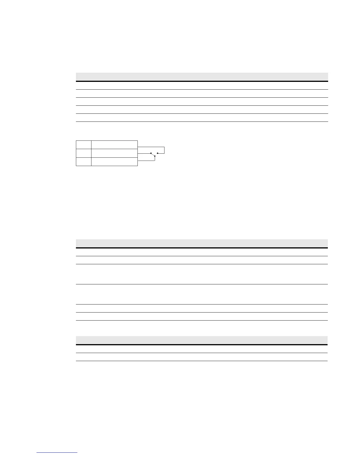
Figure 22 shows a schematic of the relay output contacts.
Common
Normally Closed
3
2
Normally Open
1
Relay Output
Figure 22. Standard Relay Port Connections
Programmable Signal Inputs
The UPS incorporates four programmable signal inputs: one RS-232 input, two connectivity card inputs, and
one REPO terminal input. See Figure 18 on page 38 for the locations of the ports. Configure the inputs with
the “Sign
al Inputs” setting in “User Settings” on page 28.
Table 9 shows the programmable settings for the signal inputs. Table 10 shows the operation logic for the
sign
al inputs.
Table 9. Programmable Signal Inputs
Signal Description
Not Used The input operates only as a serial
input (RxD) or has no function.
Force Bypass If active, the UPS is forced to static bypass op
eration regardless of the bypass status.
Remote Shutdown If active, the UPS output turns off after a user-defined
remote shutdown delay. The batteries continue
charging. Inactive input does not abort the shutdown countdown and does not cause the UPS to start up
automatically.
Delayed Shutdown
(and restart)
If active, the UPS output turns off after a user-defined
delayed shutdown delay. The batteries continue
charging. Inactive input does not abort the shutdown countdown but will cause the UPS to start up
automatically if the input voltage exists.
On Generator If active, synchronization is disable
d and the UPS transfers to bypass.
Building Alarm 1 If active, the UPS generates the “Building Alarm 1”al
arm.
Table 10. Polarity Options
Input Description
High Active state on high voltage (+Udc) level
Low Active state on low voltage (GND or -Udc) level
 Loading...