Installation
Eaton 9130 700/3000 VA UPS User’s Guide 164201718—Rev 7 www.eaton.com/powerquality 20
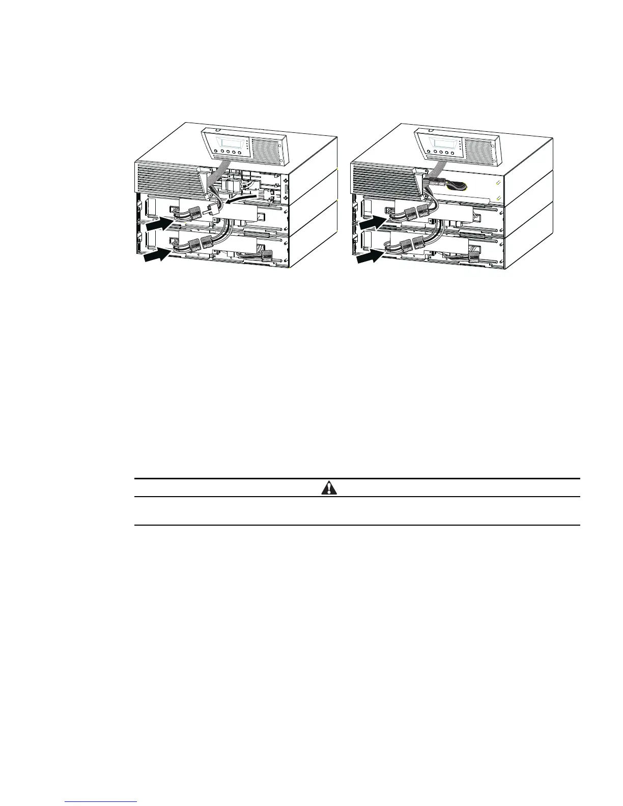
6. Verify that the EBM connections are tight and that adequate bend radius and strain relief exist for each
cable.
sledoM AV 0003–0002sledoM AV 0051 ot pU
Figure 13. Typical EBM Installation
7. Replace the EBM front cover.
To replace the cover, verify that the EBM cables are ro
uted through the EBM cover knockouts, then slide
the cover from the left to the right until it connects with the cover hook near the left side of the EBM
cabinet. Reinstall the two screws on the right side of the front cover. For reference, see Figure 12 on
page 19.
Repeat for each additional EBM.
8. Verify that all wiring connecting the UPS and EBM(s) is installed behind the front covers and is
inaccessible to users.
9. Return to Step 4 on page 18 to continue the
UPS installation.
Tower Installation
The Eaton 9130 tower cabinet comes fully assembled and ready to connect.
The cabinet is heavy (see page 56). Removing the cabinet from its carton requires a minimum of
two people.
To install the cabinet:
1. Place the UPS on a flat, stable sur
face in its final location.
2. If installing additional cabinets, place them next to the UPS in their final location.
3. Continue to the following section, “Tower Wiring Installation.”
Tower Wiring Installation
This section explains:
l
Installing the UPS, including connecting the UPS internal batteries
l
Connecting any optional EBMs
 Loading...