27
GB
Explosion-protected, light alloy Ex-d (e) control stations and
distributions, Series: GHG 64
In accordance with the approvals, the Ex-d
control stations can also be built together on a
building block principle to form distributions
using separately certified Ex-e busbar or
connection boxes of the type GHG 75. They
are mounted on wall or free-standing frames.
The electrical connection is made using
flameproof cable bushings.
The connection cables are fed into busbar or
connection boxes via cable entries in the type
of protection Increased Safety.
The minimum clearances and creepage
distances up to 10 KV in accordance with
EN/IEC 60079-7, Table 7, shall be observed.
Warning: The maximum dimensions of
the distribution must not exceed
2,18 m x 6,30m.
Applications other than those described
are not permissible without a written
declaration of consent from Messrs.
Cooper Crouse-Hinds / EATON.
The sole responsibility with respect to the
suitability and proper use of these boxes lies
with the operator.
CCH assumes no liability for damage arising
from improper use.
6 Installation
The relevant national regulations (e.g. BetriSiV,
the equipment safety law for Germany) and the
generally recognized rules of engineering apply
for the installation and operation
(IEC/EN 60079-14).
Only fully certified apparatus may be
installed and put into operation.
a The improper installation and operation
of enclosures can result in the invalidation
of the guarantee.
6.1 Mounting of Ex-d control station and
distributions
The Ex-d control station and distributions can
be mounted without opening the enclosure´s
cover. The enclosures are intended for wall
or floor mounting. When enclosures with an
optional hinge for the cover are mounted on
a wall, it is necessary to ensure that the cover
may only be swung open sideways.
The distances for flange joints of flameproof
equipment to any solid obstacles have to meet
the requirements of IEC/EN 60079-14. The
flange joint is located between the cover and
enclosure. Smaller distances than defined in
IEC/EN 60079-14 are covered by the
certification(s).
Cooper Crouse-Hinds GmbH reserves the right
using them in installations.
When the flameproof enclosures and distribu-
tions are mounted directly onto the wall or onto
wall or floor frames, they shall rest evenly
without twisting on the fastening points
provided for this purpose.
The screws and washers selected shall match
the fixing holes. The flameproof enclosure can
also be mounted using hook bolts or with
mounting brackets.
The mounting brackets can be fitted facing
upwards, downwards or sideways.
Suitable screws with a spring washer and
washer shall be used for screwing them onto
the enclosure. All the mounting brackets shall
be used when mounting the Ex-d enclosure.
The fixing dimensions can be found in the
Technical Data.
In order to mount the cover of the Ex-d
correctly, it is essential to ensure that there is
no twisting.
a Excessive tightening can damage the
flameproof enclosures.
6.2 Opening enclosure
Before opening the enclosures, it is
necessary to ensure that there is not
potentially explosive.
Before opening the enclosure, it is
necessary to ensure that the voltage
supply has been isolated or to take
suitable protective measures.
Before opening , Ex-d flameproof enclosure
with built-in load disconnect switch, set the
switch to the „ON“ position.
The enclosure cover is fixed to the enclosure
base using special screws
(up to enclosure size 7
M10 x 55,
from enclosure size 8 M10 x 65).
Enclosure without optional cover hinge:
- Loosen all screws
- After the cover screws have been loosened,
the cover can be removed by carefully sliding
it to the side.
Do not damage flameproof joints on the
enclosure cover and enclosure by making
scratches!
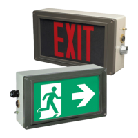
Enclosure with optional cover hinge
(Fig. 2)
After the cover screws (special screw) have
been loosened, a compression spring lifts
the enclosure cover off the enclosure body.
This allows the cover to be opened without
damaging the flameproof joint (flat joint).
The following procedure is recommended:
Loosen the cover screws and unscrew until
the screw threads barely engage in the cover.
Loosen the middle cover screw on the side of
the enclosure where the hinge is mounted last.
Do not open cover yet!
Pull out the enclosure cover on the side with
the hinge until the hinge catch disengages. This
prevents the enclosure cover from tipping to
one side. When opening the cover fully, care
shall be taken to ensure that restraining cord
does not get caught in the built-in components,
as this could damage them.
Do not put any unnecessary strain on the
hinge mechanism by opening the cover abruptly
or by placing any additional loads on the open
enclosure cover.
Fig. 2 Opening enclosure with
optional hing
 Loading...