32
D/GB
Technischer Anhang
Technical annex
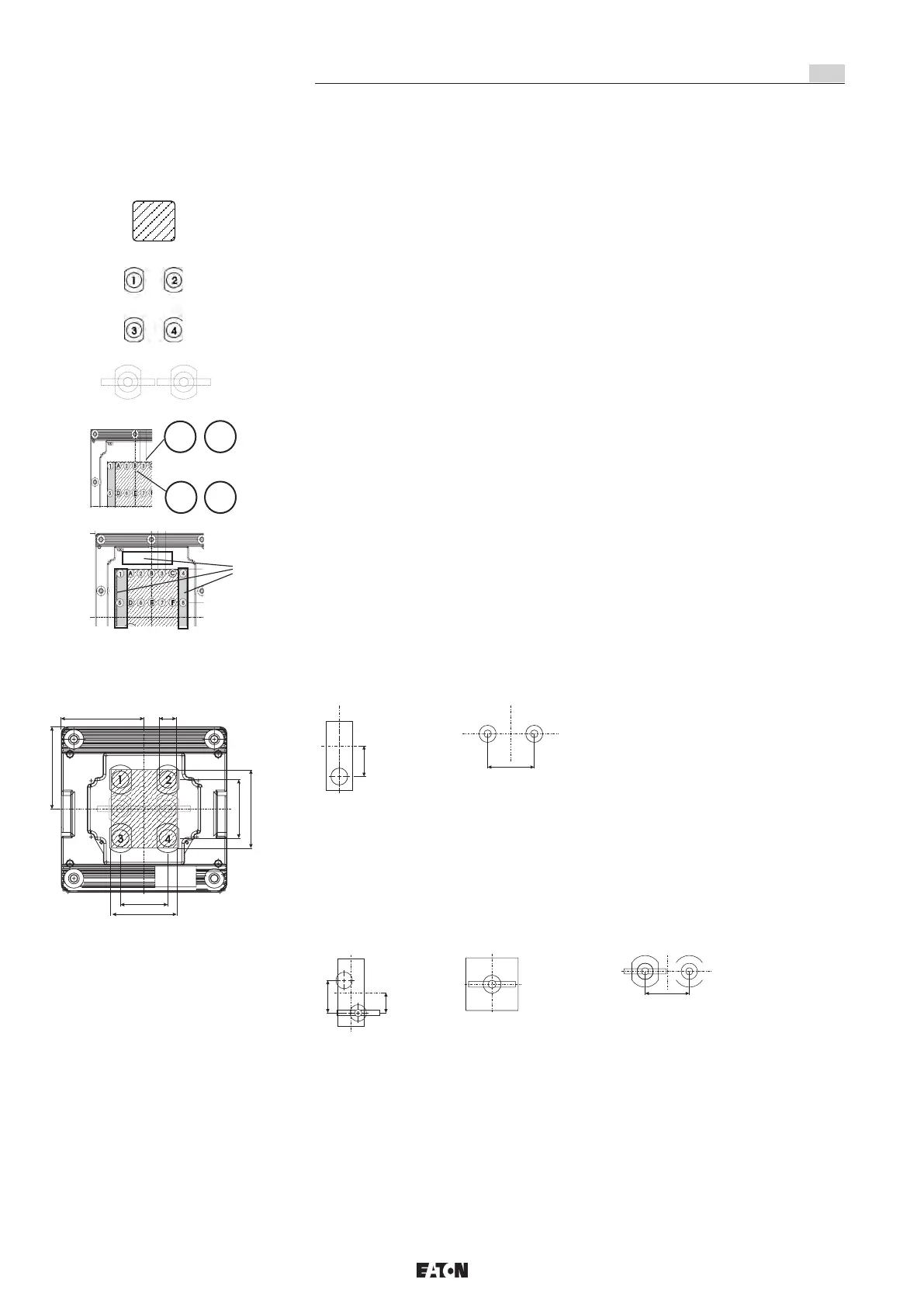
10.2 Anordnung von Bedienelementen im Gehäuseoberteil
Arrangement of actuators in enclosure cover
10.2.1 Legende für Zeichnungen
Legend for drawings
10.2.2 Fläche für Bedienelemente Größe 4 320*320
Drilling surface enclosure cover Size 4 320*320
1 poliger Automat
2 poliger Automat
3 poliger Automat
1 pole MCB
2 pole MCB
3 pole MCB
Fläche für Bedienelemete
Drilling area for actuators
Raster für Schaltervorsätze
< 20 A,
Taster und Leuchten
Distance between centres for switch
elements < 20 A,
pushbuttons and lamps
Raster für Schaltervorsätze
>= 20 A
Distance between centres for switch
elements >= 20 A
Raster 1;2;3... oder A;B;C...
für Vorsätze
Distance 1;2;3... or A;B;C...
for actuator elements
Bereich nur für Befehlsgeber/Leuchtmelder Drilling area for pushbuttons and
signal lamps only
32 A Schalter
32 A switch
2 poliger Fi
2 pole RCB
40 A Schalter
63 A Schalter
40 A switch
63 A switch
20 A Schalter
20 A switch
105
75
97
105
60
82
M22 x 1,5
1poliger Automat
2poliger Automat
3poliger Automat
4poliger Automat
27
60
60
43,1
27
2
A B
1
ODER / OR
15
11
16
2
3
14
13
12
7
8
9
10
6
5
4
1
A
B
C
D E
F
G H
I
J K
L
15
11
16
2
3
14
13
12
7
8
9
10
6
5
4
1
A
B
C
D E
F
G H
I
J K
L
 Loading...