14
Installation
Installation
Connections
Installation
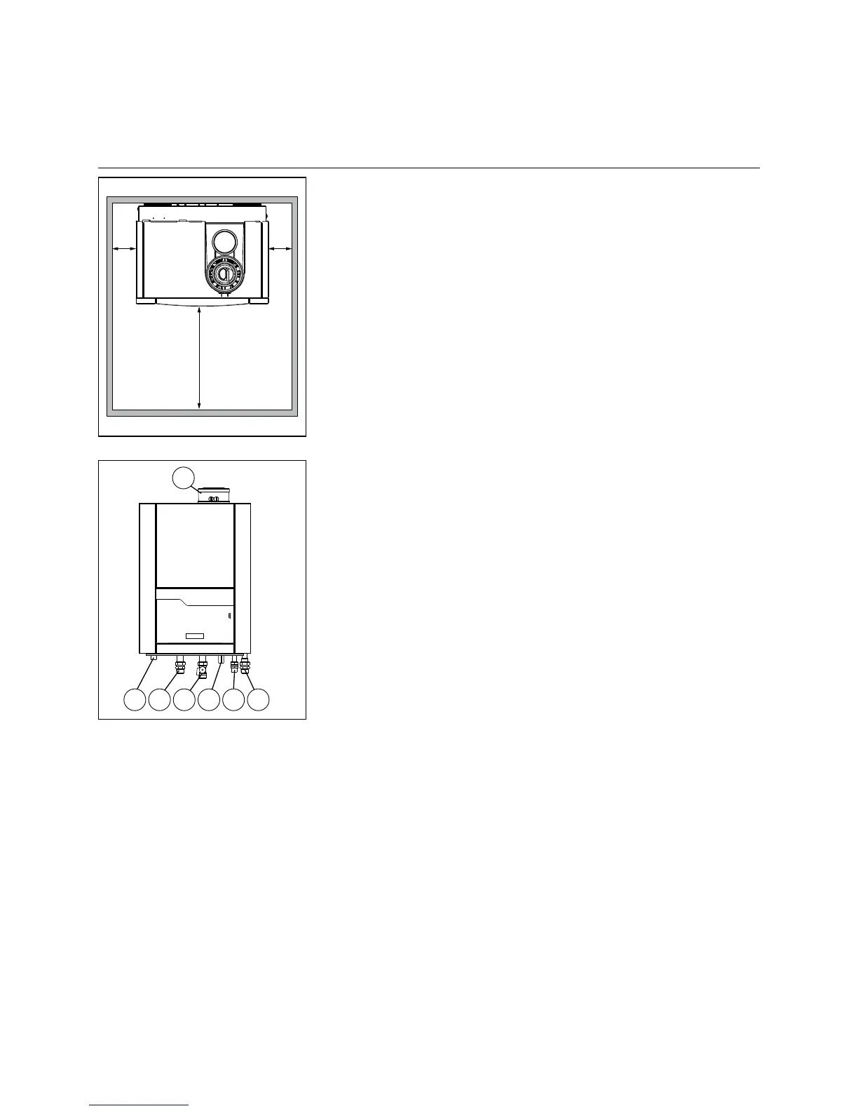
Install the boiler in a suciently
ventilated room, which conforms to
current regulations.
The boiler should always be installed
in a space protected against frost.
When setting up the boiler, please
observe the intervals recommended
on the adjacent sketch Maintenance
worksbecomemoredicult,incaseof
smaller intervals.
150mm
150mm
1000mm
Connections
The following chapter describes how
the various connection must be made
on the boiler:
- Hydraulic connections
- Condensate drainage connection
- Gas connection
- Flue gas connection
- Air supply connection
- Electrical connection
The boiler must be connected in such
a way that the system conforms to the
relevant standards and regulations
(European, national and local). It is the
responsibility of the installing technician
that these standards and regulations
are observed.
Hydraulic connections
The THISION S PLUS must be
installed in such a way so that a
prescribedminimumowisalways
ensured. In systems where the
radiatorsarettedwiththermostatic
valves, it is recommended to install
a pressure operated by-pass valve
downstream of the last radiator on
theheatingcircuit,oradierential
pressure by-pass valve (available as an
accessoryitem)betweentheow(1)
and return (2) pipes.
The boiler contains an installed safety
valve of 3 bar. The drain of the safety
valve has an open connection to the
condensate drain.
There are connection possibilities for
an(optional)lling/emptyingcockand
a connection to an expansion vessel
(3).Thelling/emptyingcockand
connection to an expansion vessel
should be made in the return pipe of
the boiler. The Combi 24 model has an
installed expansion vessel of 12 litres.
Condensate connection (4)
Connection to the drainage system
is always installed in an “open”
fashion,sothatareuxintotheboiler
is avoided, in case of a stopped up
drainage system.
Gas connection (5)
The type plate of the THISION S PLUS
has been attached at the factory on the
left-hand side of the boiler system (after
removal of the panelling). The gas
type (natural gas or liquid gas) must
conform to the information on the type
plate, which contains the installation
information for the boiler.
The connection of the system to gas
mustbecarriedoutbyancertied
technician. Here too, the national and
local standards and regulations are
applicable.
The gas pipe must be attached leak-
proof to the gas connection (6) of the
boiler. It is recommended to install
a gas meter behind the THISION S
PLUS system.
Agasltercanbemounteddirectlyon
the gas connector.
Connection for the DHW tank return
connection (6).
Air supply / waste gas ow (7).
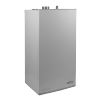
5 1 4 3 6
7
2
1 Boilerowconnection
2 Boiler return connection
3 Expansion vessel
4 Condensate drain
5 Gas
6 DHW tank return connection
7 Airsupply/uegas
 Loading...