25
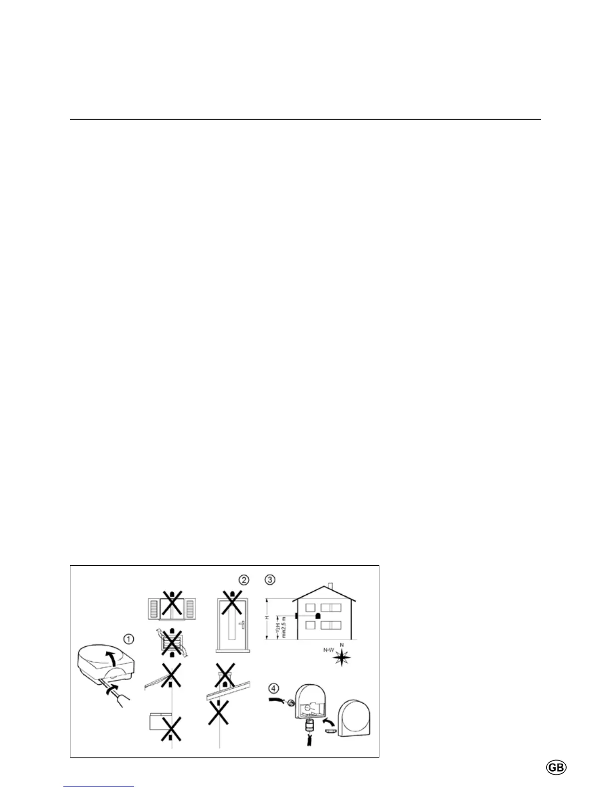
Installation of outdoor sensor
If an outdoor sensor is connected
to the boiler, then the sensor must
be positioned in conformity with the
adjacent drawing.
If an outdoor sensor is not connected,
then please proceed that to set
parameter 6120 to ‘OFF, and save this
setting with the parameter 6200.
This helps to avoid error number 10
(outdoor sensor).
Electrical connection
Electrical connections must be
carried out by an authorized electrical
technician, and in conformity with
valid national and local standards and
regulations.
An insulated mains switch must be
used for the power supply, with at least
3 mm contact openings. It must be
mounted inside of the boiler room. The
mainsswitchisusedforswitchingo
the power supply during maintenance
works.
All cables are passed through the cable
gland at the bottom of the boiler, and
are led to the electronics panel at the
front of the boiler.
The electric diagram must be observed
during all electrical connection works
(see the following pages).
CAUTION:
Ensure that the right polarity is used
for the equipment.
If malfunction 133 occurs during
commissioning of the facility, then,
as a rst step, the polarity of the
electrical connection must be tested,
after which the boiler can be taken
into operation again.
Installation
Electrical connection
 Loading...