23
Flue gas connection
We recommend the use of ELCO’s
comprehensiverangeofuegas
components.
For further information, please see the
installation instructions:
- ELCO wall terminals
- ELCO roof terminals
- ELCOuepipecomponents,both
individual pipes and concentric
tubes.
Regulations about the construction
andinstallationofuegassystemsare
dierentfromcountrytocountry.
It must be ensured that all national
regulations with regard to chimney
systems are observed.
Notes
The tables below give guidance on
themaximumlengthsofairandue
gas tubes that may be connected. If
a room sealed installation is being
madeutilisingseparateairanduegas
tubes, the lengths of both tubes must
be added together and not exceed the
relevant value given in the tables.
Inallcases,theconcentricue/air
connection on the top of the boiler
case is 80/125. When using 110/150
uecomponents,anallowancefor
the necessary 80/125 to 110/150
adaptorttinghasbeenincludedin
theuelengthsindicatedinthetables.
The maximum length of any external
sectionofuepipemustnotexceed
5m.
Theradiusofanybendusedintheue
gas system must not exceed 87.5°.
Installation
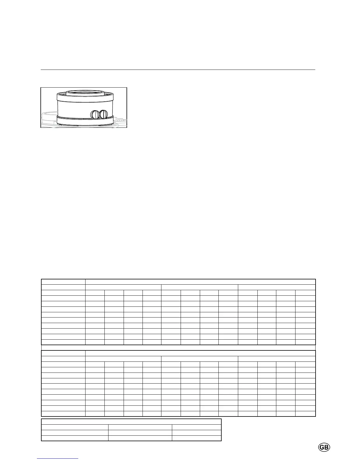
Connections
Air- / ue gas ducts
All boiler models have an ø80/125
concentricueconnection.
Required minimum (ue enclosure) shaft cross-section
Diameterueduct Square shafts Round shafts
80 mm 120 x 120 mm 130 mm
110 mm 140 x 140 mm 160 mm
It is not necessary to install a separate
condensatedrainfortheuegas
system, since the condensate will be
ushedoutviatheboilerandintothe
siphon. Please observe the following
recommendations:
- Only use corrosion-resistant
material
- The diameter must be calculated
and selected according to the
national regulations.
- Thelengthoftheuegassystem
must be kept as short as possible
(and must not exceed the
maximum permitted length, see the
documentation for planners)
- Horizontaluegastubesmusthave
an inclination of at least 3° back
towards the boiler.
Air supply connection
If required, a separate room sealed
air supply tube may be connected
via the inclusion of the optional air
supplyconnectortting.Thediameter
must be calculated in conformity with
national regulations and in combination
withtheuegasgassystem.The
overall resistance of the air supply
anduegastubesmaynotexceed
the maximum supply pressure of the
Fan at any time. (Also see the Chapter
“Technical data”)
Dimensioning (reference value)
Maximum length in metres of D80 and D110 Ø tubes (open or parallel tubes room sealed installation)
D 80 mm D 110 mm
Changes of direction 0 2 3 4 0 2 3 4
13 60 58,6 57,9 57,3 80 79,5 79,3 79,0
19 60 57,6 56,5 55,3 80 79,2 78,7 78,3
24 60 56,5 54,8 53,0 80 78,8 78,1 77,5
Combi 24 60 56,6 54,9 53,2 80 78,8 78,2 77,6
34 30 22,0 18,0 14,0 80 77,1 75,7 74,3
Combi 34 30 22,0 18,0 14,0 80 77,2 75,8 74,4
35L 12 3,6 55 52,0 50,5 49,1
46 12 55 49,9 47,3 44,7
54 11 50 42,9 39,3 35,8
Maximum length in metres for concentric room sealed installations D 60/100, D 80/125 and D 110/150
D 60/100 mm D 80/125 mm D 110/150 mm
Changes of direction 0 2 3 4 0 2 3 4 0 2 3 4
13 14 8,8 6,2 3,6 40 38 37 36 40 39 38,5 38
19 14 5 0,5 40 36,6 34,9 33,2 40 38,2 37,3 36,4
24 14 0,6 40 35 32,5 30 40 37,4 36,1 34,8
Combi 24 4 0,6 25 35 32,5 30 40 37,4 36,1 34,8
34 4 25 13,6 7,9 2,2 40 34,2 31,3 28,4
Combi 34 4 25 13,6 7,9 2,2 40 34,2 31,3 28,4
35L 4 12 0,2 40 33,8 30,7 27,6
46 12 30 19,4 14,1 8,8
54 11 30 15,4 8,1 0,8
 Loading...