02/02
13
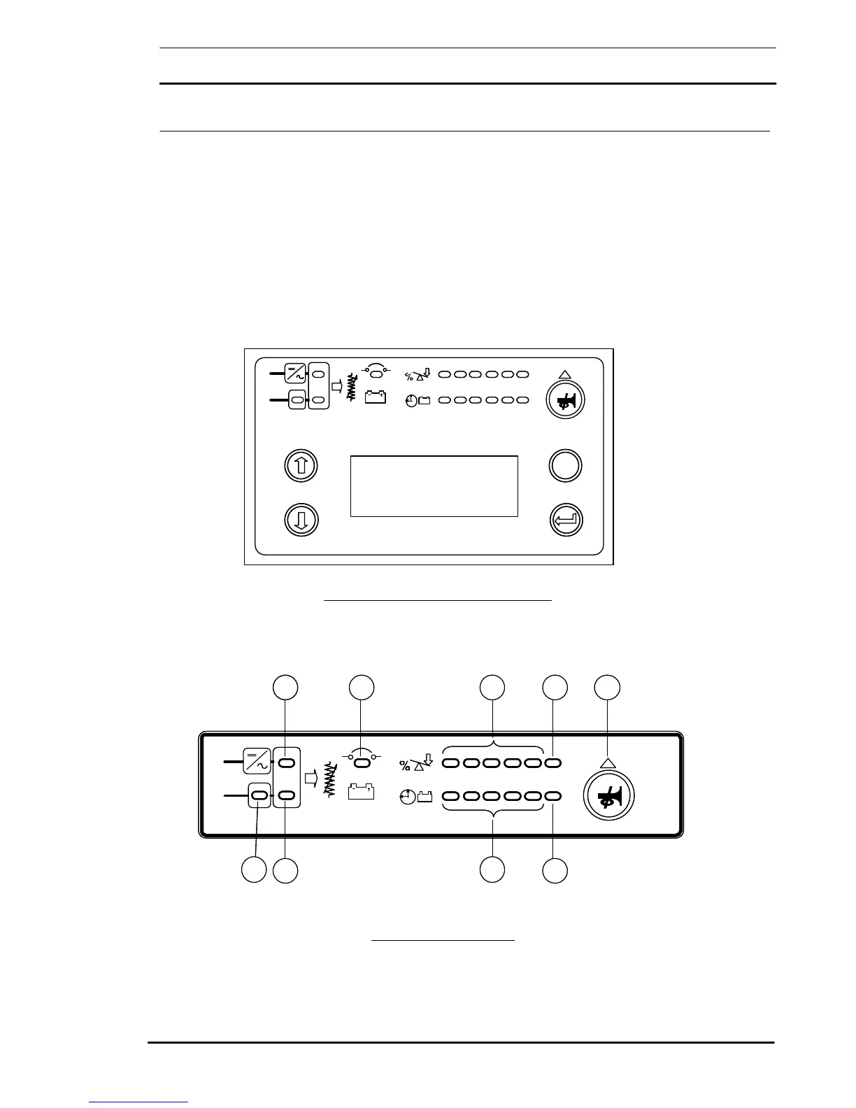
1.3 Operator Control and Display Panel
The operator control and display panel can be divided into two
functional sections: ‘LED Indications’ and ‘Control and Display. As
can be seen the upper section consists of LEDs which indicate the
operational and alarm status of the system by turning ON and OFF or
by flashing ON / OFF. This section can be further split into five
separate areas as identified in figure 1-4.
The lower section of the operator control and display panel consists of
a LCD (Liquid Crystal Display) and its associated switches.
Figure 1-4: Operator Control/ Display Panel
Figure 1-5: LED Indications
Esc
7400 M
UNITERRUPTIBLE POWER SUPPLY SYSTEM
Esc
7400 M
UNITERRUPTIBLE POWER SUPPLY SYSTEM
3
6
8
1
2 4 5 97
3
6
8
1
2 4 5 97
 Loading...