02/02
55
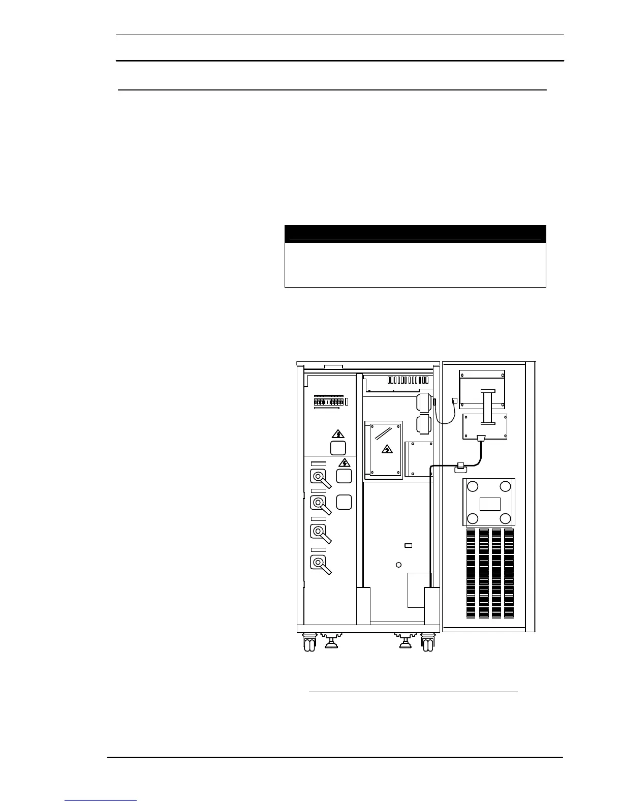
4.7 Communication Kits
The Communication kits offer the necessary cable assembly and
fixings connections into the communications socket (X8) on the
Operator logic board # 100204012220 to a DB25 male connector
(X4), located adjacent to the cable access panel as shown in figure 4-
11.
Using the wiring configurations shown in figure 4-12 the UPS can be
connected to either a personal computer of a modem.
See manual include in the kit.
Caution
Note: The communications wiring for this option must be kept
separate from the power wiring. This is to maintain the
integrity of “Safety Extra Low Voltage” (S.E.LV.) circuits.
Figure 4-11: Installing the RS232 communication cable
# 100204012220
X8
 Loading...