02/02
15
Switch - Emergency Power Off (EPO):
The optional EPO switch is located remote to the UPS cabinet in a
position agreed with the user. When the EPO switch is pressed it
disables the static switch block entirely (so removing load power). It
also disables the rectifier and inverter, and trips the battery circuit
breaker. Under normal circumstances it does not remove UPS input
power since this is applied through a manually controlled external
isolator; however, if the UPS input supply is connected via a circuit
breaker having an electrical trip facility, emergency power off and
other (insulated) section can be used to drive the external circuit
breaker's trip circuit.
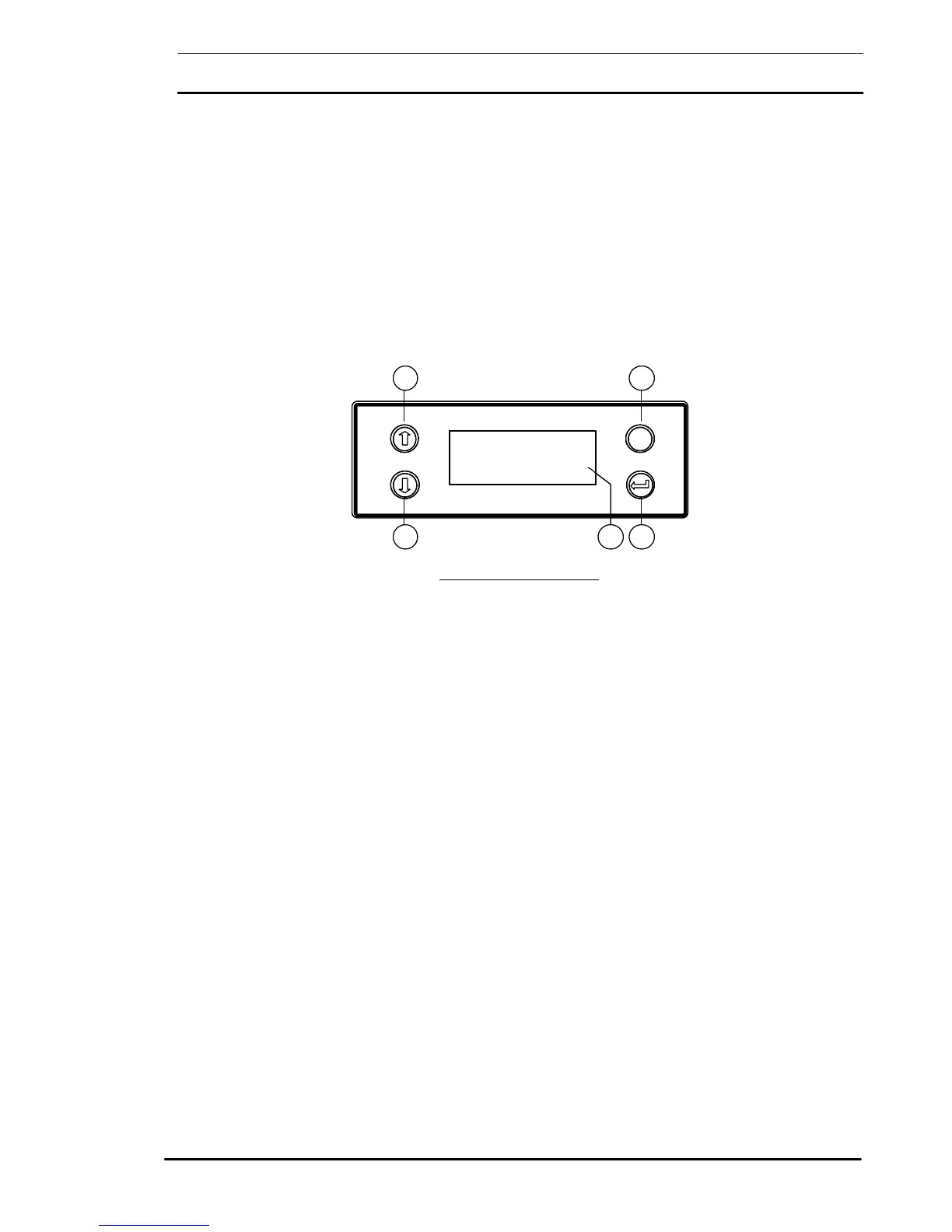
The LCD consists of a window and four push buttons. The display is
capable of showing 4 rows of 20 characters and is used to indicate the
UPS operating parameters, warnings and alarms. The push buttons
permit the operator either to select options from a menu for display
on the window, or else to charge the value of certain parameters.
ENTER (4)
Pressing ‘ENTER’, when selecting options, displays the next window.
The next window is determined by the option, which has been elected
in the present window. When selecting new parameters, it saves the
new parameters.
ESCAPE:
Pressing ‘ESCAPE’ cancels the most recent actions, i.e. when selecting
options, it returns the previous window to the LCD; when setting
parameters, it exits the window without saving the new settings.
UP (1)
The UP push button moves a cursor up the LCD over the options
offered on certain windows, and moves a rectangular cursor to the
next digit on the right when changing parameter values in others.
DOWN (2)
The DOWN pushbutton moves a cursor down the LCD over the
options offered on certain windows, and changes the highlighted
parameter values in others.
Figure 1-5: LED Indications
Esc
1 5
7400 M
UNITERRUPTIBLE POWER SUPPLY SYSTEM
2 43
Esc
1 5
7400 M
UNITERRUPTIBLE POWER SUPPLY SYSTEM
2 43
 Loading...