02/02
34
The input mains/bypass cables, UPS output cables and battery cables
Connections (all require lug type terminations) are connected to
busbar situated between the power isolator switches - as shown in
figure 3-5. A terminal block X3 is used for connecting the control
cables to the battery circuit breaker and the external emergency stop
facility, these are female spade type connections (Fast-on 6,3x0,8).
3.3.4 Safety Earth The safety earth bus-bar is located near the input and output power
supply connections as shown in the following diagram, The safely
earth cable must be connected to the earth bus-bar and bonded to
each cabinet in the system.
All cabinets and cable trunking should be earthed in accordance with
local regulations.
WARNING
FAILURE TO FOLLOW ADEQUATE EARTHING PROCEDURE
- CAN RESULT IN ELECTRIC SHOCK HAZARD TO
PERSONNEL, OR THE RISK OF FIRE, SHOULD AN EARTH
FAULT OCCUR.
3.3.5 Protective Devices Bypass Input of UPS: is not self-protected against overloads or shorts
circuits: it's necessary to install in distribution panel a circuit breaker or
fuses to protect bypass line.
Rectifier Input : it's the same, in case of separate rectifier input, it's
necessary to install in distribution panel another circuit breaker or
fuses to protect input wires.
Output of UPS : an insulator switch may be inserted in distribution
panel for maintenance purpose; be sure don't use a protective device
for the whole output power of UPS, in particular don't use RCCB.
(Residual Current Circuit Breaker)
Protective devices may be used for distribution lines to loads, be sure
that they are selective with protecting devices in input of UPS.
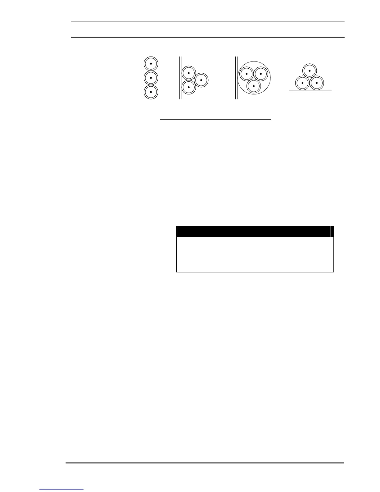
Sheathed cables clipped
direct to or lying on a
non – metallic surface
Figure 3-3: Cable fixing samples from method 1
 Loading...