02/02
45
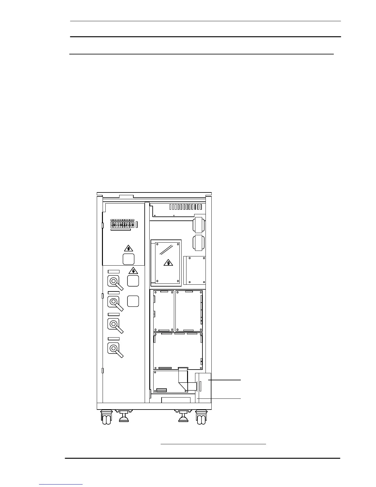
4.2 Remote Alarms Interface Board ( # 100201120007)
4.2.1 Alarm Outputs The Remote Alarms Interface board is fitted in the right hand side of
the unit as shown in figure 4-3 and is connected (piggy back style)
directly via connector X1 onto the Interface Board connector X2. This
board therefore can only be used in conjunction with the Interface
Board (100201120003).
The Remote Alarms Interface board contains a number of relays
driven by alarm signals generated within the UPS, whose contacts
provide a set of volt-free alarm outputs that are connected to terminal
blocks X2 and X3 - as shown in figure 4-4. These outputs can be used
to drive an external alarms monitoring device.
Maximum contact rating on M1 terminals 50 Vcc @ 1 Amp.
Note: When using the above contacts for remote alarm annunciation, the
power supply for the remote indicators must be provided from an external
power source. Under no circumstances should the UPS internal low
voltage supplies be used for this purpose.
Remote alarms Interface Board
# 100201120007
Alarm Interface Board
# 100201120003
# 100204011020
# 100201120001
# 100218031020
# 100209011020
# 100221011030
 Loading...