EasyManuals Logo
Home>Emerson>UPS>7400M Series

Emerson 7400M Series User Manual

Emerson 7400M Series
86 pages
To Next Page IconTo Next Page
To Previous Page IconTo Previous Page
Page #79 background imageLoading...
Page #79 background image
02/02
78
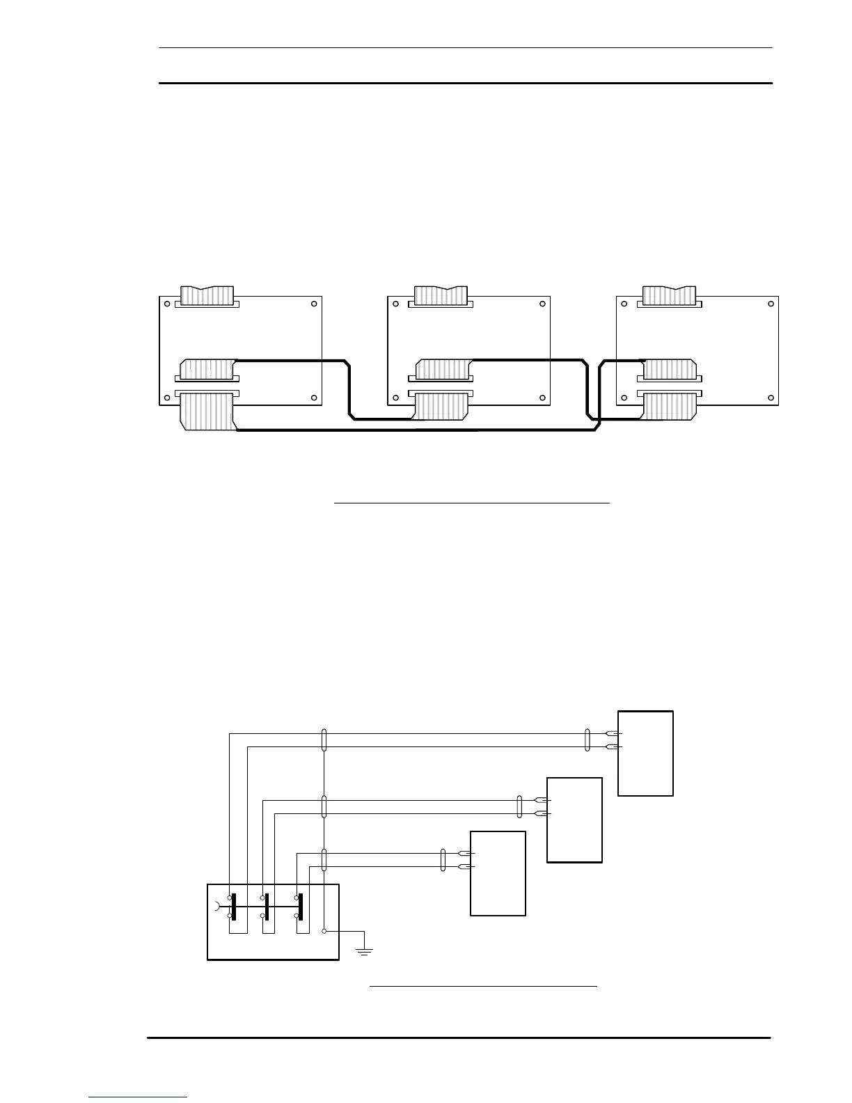
7.3.3 Control Cables Parallel bus
Each module has it Parallel Board (# 10021620028) connected with
the other via two shielded 34-poles flat-cables.
The connection is redundant, disconnecting one cable lits a red LED
on Parallel boards, disconnecting both cables inverter are blocked
(this last function may be disabled during servicing of the system).
Cables must be crossed connecting one module to the other.
Figure 7-4: Connection of Parallel Signal Bus Cables
Figure 7-5: Connection of EPO Push button
Emergency Power Off (EPO)
It's suggested to use an emergency power off push button with two
separate and insulated ways, so it'
s possible to power off both modules
at the same time.
A third insulated way may be used to trip input breakers of distribution
panel. Its needed to power off also inputs of modules.
For EMI reasons cabling must be shielded and shield must be grounded
at EPO side.
7400M
-
Series UPS User Manual
Single Module and 1+N Parallel System
X
X
X
FC (60 Poles) to X7
M o d u l
P a r a l l e l B
X
X
X
FC
(60 Poles) to X7
M o d u l
P a r a l l e l B
FC
FC
X
X
X
FC (60 Poles) to X7
M o d u l
P a r a l l e l B
FC
X3
10
11
X3
10
11
EPO Push button
Module 3
Module 2
X3
10
11
Module 1
X3
10
11
X3
10
11
EPO Push button
Module 3
Module 2
X3
10
11
Module 1

Table of Contents

Questions and Answers:

Question and Answer IconNeed help?

Do you have a question about the Emerson 7400M Series and is the answer not in the manual?

Emerson 7400M Series Specifications

General IconGeneral
BrandEmerson
Model7400M Series
CategoryUPS
LanguageEnglish

Related product manuals