1.3 Appearance And Components
1.3.1 Appearance
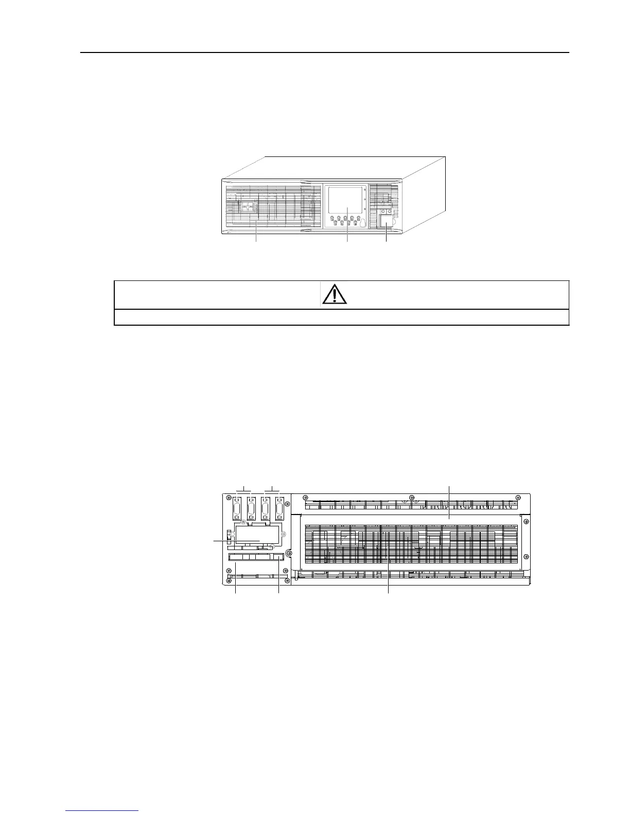
The UPS appearance is shown in Figure 1-1.
Ventilation
holes
Operation
and
display panel
DIP switch, battery cold start
button
(with protective cover)
Figure 1-1 UPS appearance
Note
Non-authorized personnel are prohibited from opening the UPS chassis cover. Otherwise, electric shock may occur.
1.3.2 Components
Front
p
a
n
e
l
As shown in Figure 1-1, the UPS front panel provides ventilation holes, operation and display panel, DIP switch and
battery cold start button (with protective cover). The operation and display panel provides LCD, menu buttons, LED
indicators and control buttons. Refer to Chapter 3 Operation And Display Panel for details.
Rear
p
a
n
e
l
As shown in Figure 1-2, the UPS rear panel provides parallel ports, load bus synchronization (LBS) ports, dry contact
I/O port, SNMP card port, USB port, I/O terminal block and ventilation holes.
Parallel ports
LBS ports
I/O terminal block (with protective cover)
SNMP card
port
(with
protective cover)
Dry contact I/O port USB port
Ventilation
holes
Figure 1-2 UPS rear panel
 Loading...