Note
When the parallel system uses the shared battery, the ‘Single Group Batt Cap’ of the LCD setting of each UPS single stands for
the gross capacity of battery string, and each single can calculate the battery capacity itself automatically.
3. Close the battery MCB of each single.
2.10 Double Bus System
2.10.1 System Installation
The double bus system is composed of two independent UPS system, and each UPS system can be composed of
one or two parallel UPS singles. The double bus system has high reliability, which is suitable for the load with many
input terminals. For single input load, you can add a selected static trigger switch (STS) to start the load bus
synchronization (LBS).
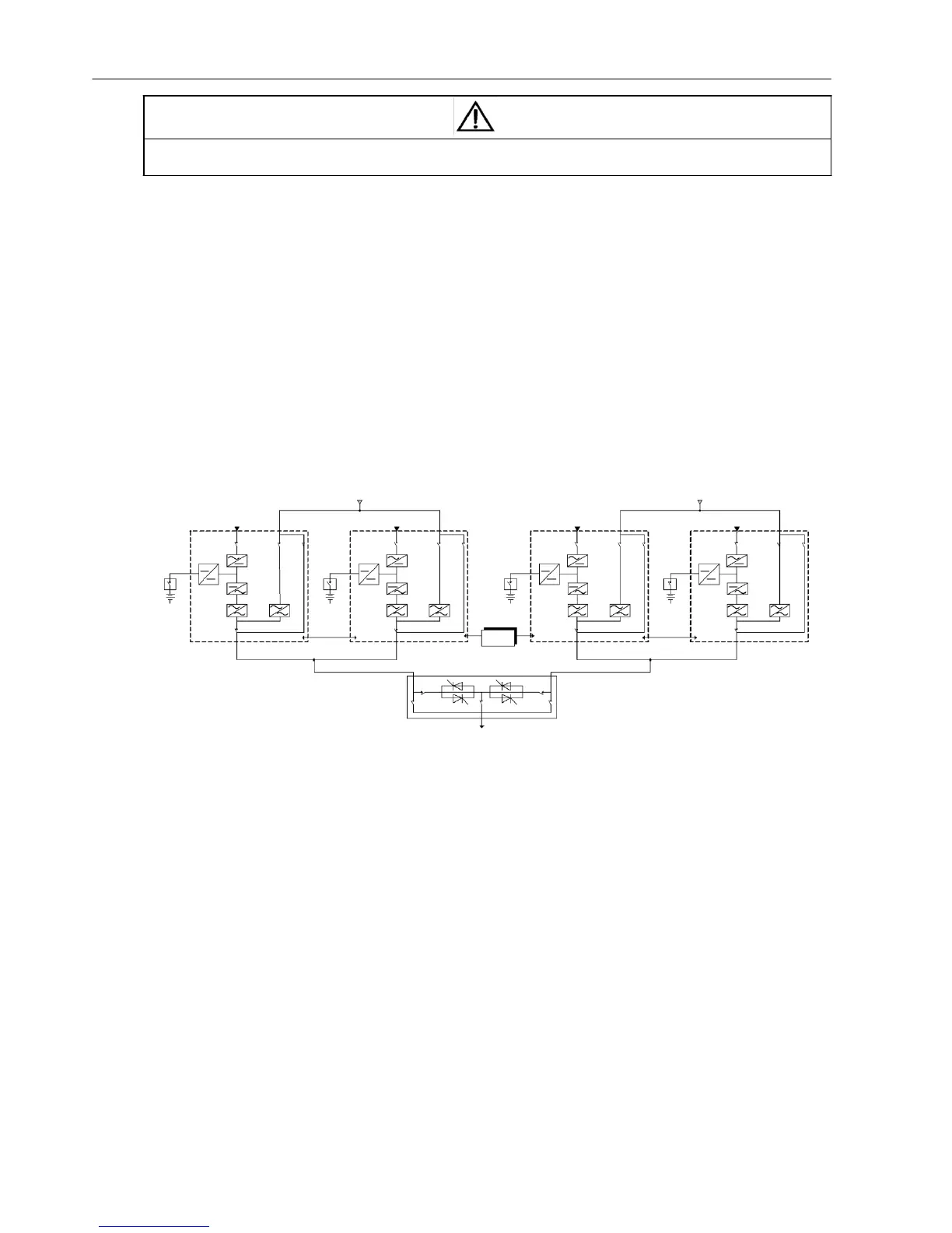
The double bus system uses LBS to realize the output sync of the two independent (or parallel) UPS systems. One is
the main system, and the other is the slave system. The operation mode of the double bus system contains main
system and/or slave system for running in Normal or Bypass mode. The typical double bus system is shown in Figure
2-20.
Rectifier input
UPS1
Bypass
UPS2
Rectifier input
Rectifier input
UPS1
Bypass
UPS2
Rectifier input
Parallel
control
cable
LBS
Parallel
control
cable
STS
Load
connection
Figure 2-20 Typical double bus system (with the STS and LBS)
2.10.2 External Protective Device
See 2.5 External Protective Device.
2.10.3 Power Cables
See 2.6 Connecting Power Cables.
2.10.4 LBS Control Cables
Just connect the LBS cables respectively to any two LBS ports (see Figure 1-2) of the two parallel systems.
 Loading...