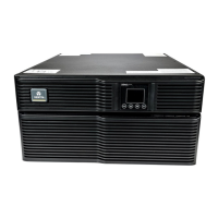
1 + 1 parallel POD (1 piece)
UPS (2
pcs)
Battery module (4 pcs)
Figure 2-18 1 + 1 parallel system including battery modules
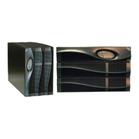
2.8.2 Setting Parallel Addresses
The parallel addresses for all the UPS singles in parallel system should be set. The parallel addresses can be set
through the DIP switch on the UPS front panel (see Figure 1-1). Remove the DIP switch protective cover, and set the
DIP switch according to Table 2-5. The parallel address must be unique for each UPS single.
Table 2-5 DIP switch settings
Parallel addresses Parallel 1# Parallel 2# Parallel 3# Parallel 4#
DIP switch position
ON
DIP1 DIP2 DIP3 DIP4 DIP5
ON
DIP1 DIP2 DIP3 DIP4 DIP5
ON
DIP1 DIP2 DIP3 DIP4 DIP5
ON
DIP1 DIP2 DIP3 DIP4 DIP5
Warning
The default setting for DIP switch is’1’, you can set the DIP switch to 2, 3 or 4. However, you should set the DIP switch position
according to the description listed in Table 2-5. Otherwise, the UPS fault will occur!
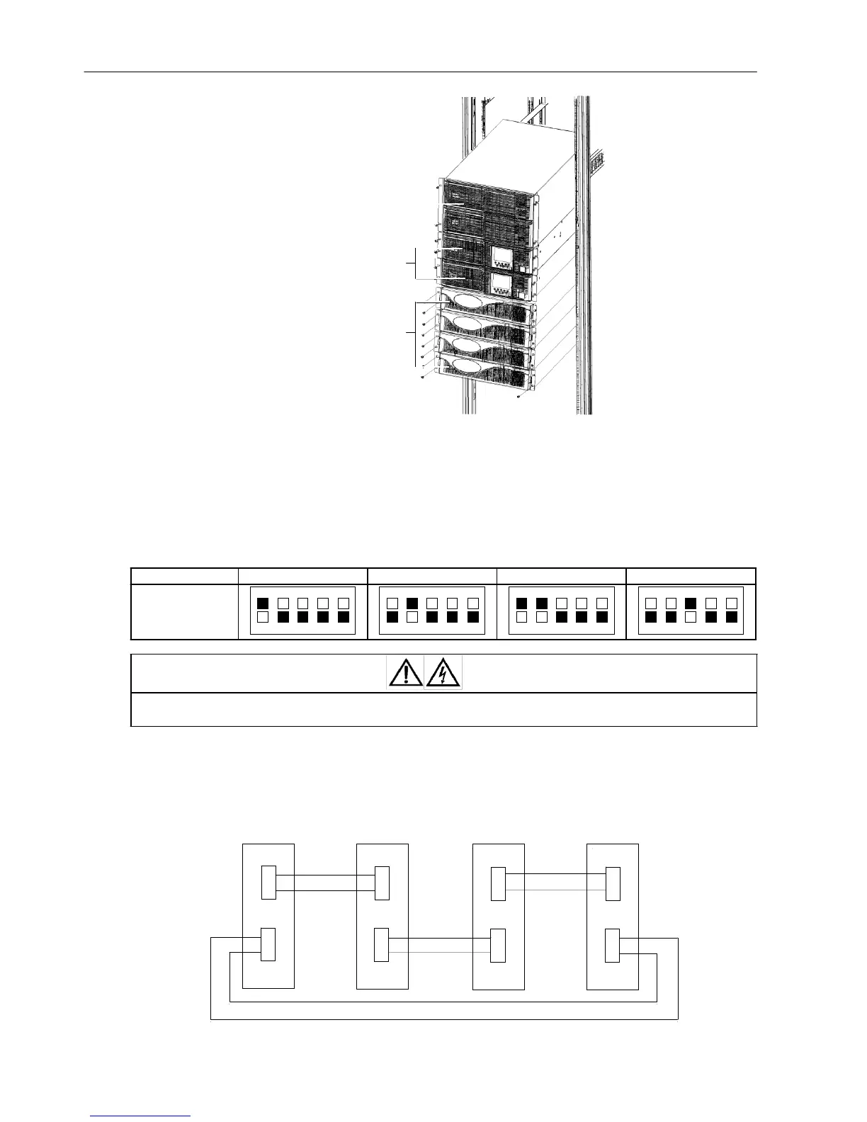
2.8.3 Connecting Parallel Cables
The parallel system provides the parallel cable options. Through the parallel ports (see Figure 1-2) on the UPS rear
panel, the parallel cables are connected in close-loop mode one by one. Taking the 3 + 1 parallel system for example,
the schematic diagram of the parallel cables connection is shown in Figure 2-19.
UPS1 UPS2 UPS3
UPS4
Parallel cable Parallel cable
Parallel
port
1
P
arallel
port 1
Parallel
port
1
Parallel
port
1
Parallel cable
Parallel
port
2
Parallel
port
2
Parallel
port
2
Parallel
port
2
Parallel cable Parallel
cable
Figure 2-19 Parallel cables connection schematic diagram (3 + 1 parallel system)
 Loading...