1. PE line: Use the shortest wiring route when connecting the cabinet earth cable. The cross sectional area (CSA) of
the earth cable should be selected according to the AC power fault level, cable length and protection type. From
AS/IE
C60950-1
,
t
he
CSA is 10mm
2
(20kVA, 3-in 3-out), 25mm
2
(20kVA, 3-in 1-out) as usual.
2. When selecting the battery cables, according to the current value shown in Table 2-2, the Max allowable voltage
drop is 4Vdc. Do not ring the cables, so as to avoid increasing the electrical magentic interference (EMI).
2.6.2 Connecting I/O Cables
Distribution
mode and terminal
b
l
o
ck
1. Distribution mode
There are two modes for UPS distribution: single power output distribution (POD) unit options provided by Emerson,
external distribution by the user.
According to the actual requirements, the I/O cable connections are divided into four types: 3-in 3-out,
common
source
configuration (factory default), 3-in 3-out, split-bypass configuration, 3-in 1-out, common source configuration,
3-in 1-out, split-bypass configuration. In accordance with the four types of the two distribution methods, this section
will introduce the I/O cables connection procedures respectively.
Note
This product is compatible with 3-in 3-out/3-in 1-out, factory default: 3-in 3-out. Change the format according to the following steps,
if you need the 3-in 1-out system:
1. After the 3-in 1-out I/O connections are finished by following the instructions in this section, power on the system, then press the
emergency power off (EPO) button immediately.
2. Set the system to ‘Single Phase Output’ through the LCD menu ‘Settings’ -> ‘3-in 3-out/3-in 1-out’.
3. Power off the system completely, then power it on again, the system will run in 3-in 1-out mode.
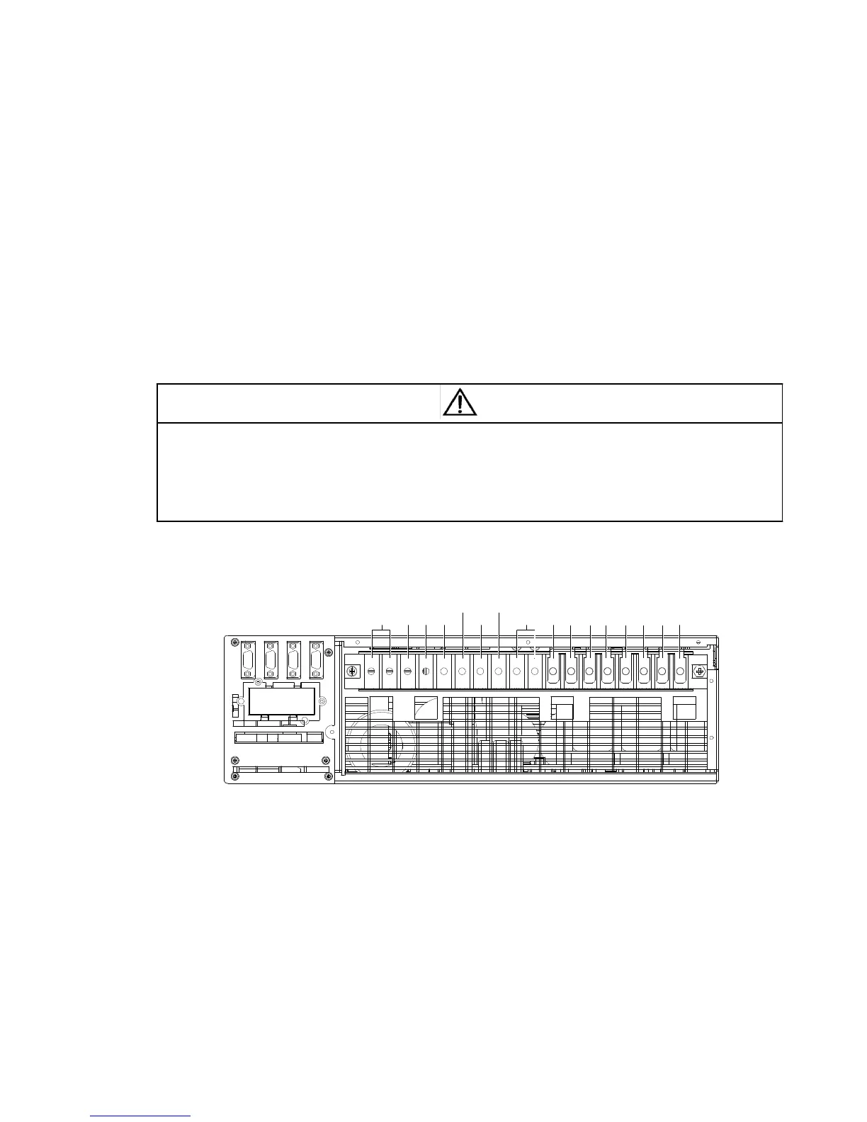
2. Terminal block
The power cables connection of the UPS should be connected through the I/O terminal block located on the UPS rear
panel. Figure 2-7 gives the terminals distribution of the I/O terminal block.
Bat
+
Bat -
oN
oA oB
oC
Bat N
PE
mN bN
mA
bA mB bB mC bC
3
3
3
3
Note: 1. Main input: mA, mB, mC, mN; Bypass input: bA, bB, bC, bN
Output: oA, oB, oC, oN; Battery: Bat +, Bat N, Bat -; GND: PE
2. In factory, four shorted copper bars 3 have been used to short terminals between mA and bA,
mB and bB, mC and bC, mN and bN respectively
Figure 2-7 Terminals distribution of the I/O terminal block
 Loading...