1) Take out the UPS options and select battery cables, insert the battery cables marked with ‘Battery Module 1’,
‘Battery Module 2’, ‘Battery Module 3’ and ‘Battery Module 4’ respectively into any battery port on the rear panel of
the four battery modules (see Figure 2).
2) Ground one end of the battery cable marked with ‘UPS PE’.
3) Connect the other end of the battery cables marked with ‘BAT +’, ‘BAT N’, ‘BAT -’ respectively to ‘Bat +’, ‘Bat N’,
‘Bat -’ terminals of the UPS I/O terminal block (see Figure 2-7).
4) Tighten the fixing screws on both battery port sides of the battery module through screwdriver, so as to prevent the
battery cable from loosing or coming off.
•
Non-selected battery
modu
l
es
Connect the external battery with terminals ‘+’, ‘N’ and ‘-’ respectively to ‘Bat +’, ‘Bat N’ and ‘Bat -’ terminals of the
UPS I/O terminal block (see Figure 2-7).
Note
1. It is prohibited to reverse the positive pole and negative pole of the battery.
2. Before replacing the battery module and connecting the battery cables, ensure that the UPS system is in maintenance mode.
3. The length of the battery cable option is 1.5m. If you need more length cables, please consult the dealer. It is recommended that
the battery cable be shorter than 3m. Otherwise, the UPS cannot operate normally.
2.7 Connecting Communication Cables
Communication cables include: dry contact communication cable, USB communication cable and SNMP card
communication cable.
All communication cables are the dual insulation cables which must be separated from the power cables for wiring.
When the longest connection distance ranges from 25m to 50m, the CSA should be ranged from 0.5mm
2
to 1.5mm
2
.
2.7.1 Connecting Dry Contact Communication Cable
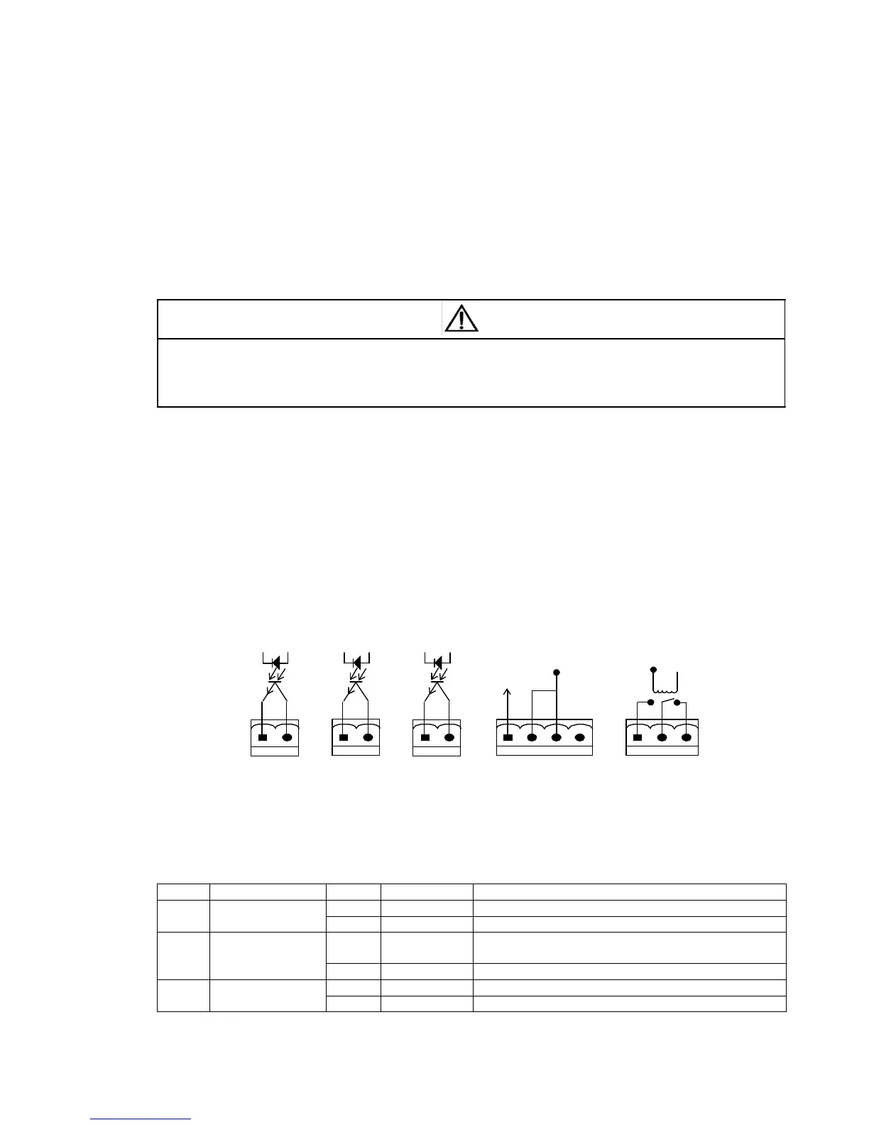
The UPS provides five dry contact ports, see Figure 1-2 for specific positions. The silkprints of the five dry contact
ports are 1, 2, 3, 4, 5. The pin distribution of each dry contact port is shown in Figure 2-16, and the port description is
shown in Table 2-3.
+12V
 Loading...