AGL_HA_ST_Discus_A2L_A1_EN_Rev00 11
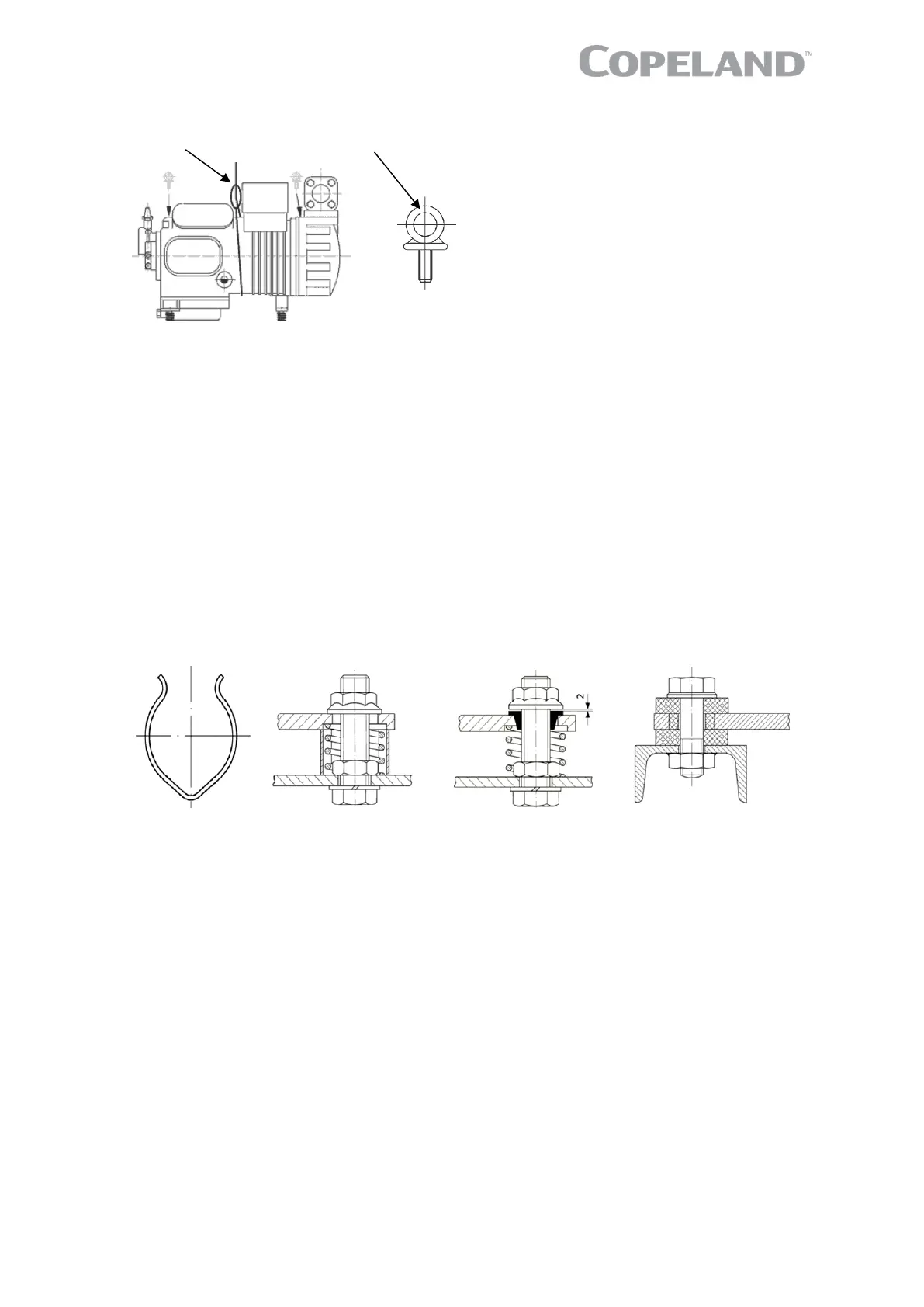
8D* Lifting eye
max. 350 kg ½" – 13 UNC
Figure 13: Compressor lifting methods
3.1.4 Installation location
Ensure the compressors are installed on a solid level base.
For multiple compressor parallel configurations, the compressors must be positioned completely
vertically on a totally horizontal surface or rail.
3.1.5 Mounting parts
To minimize vibration and start/stop impulses flexible mounting should be used. For this purpose one
specific set of spring mounting parts is delivered with each compressor model.
A compressor may be rigidly mounted, ie, without springs. In this case more shock and vibration
loading will be transmitted to the frame.
If the installation requires a very high level of vibration absorption, additional vibration absorbers –
available on the market – can be fitted between the rails and the foundation.
To ensure proper lubrication of moving parts, the compressor should be installed horizontally on both
axes.
Transport clamp Transport position Operating position Grommets for twin
compressors
Figure 14: Position of vibration dampers during transport and operation
3.2 Pressure safety controls
3.2.1 High-pressure protection
Applicable regulations and standards, for example EN 378-2, shall be followed to apply appropriate
control and ensure that the pressure never exceeds the maximum limit.
High-pressure protection is required to stop the compressor operating outside the allowable pressure
limits. The high-pressure control must be installed correctly, which means that no service valve is
allowed between the compressor and the pressure protection.
The high-pressure cut-out setting shall be determined according to the applicable standard, the type
of system, the refrigerant and the maximum allowable pressure PS.
The high-pressure cut-out should have a manual reset feature for the highest level of system
protection.

 Loading...