16 AGL_HA_ST_Discus_A2L_A1_EN_Rev00
4.2 Electrical installation
Conductor cables! Electrical shock hazard! Shut off power supply before
undertaking any task on electrical equipment.
Ignition source in a potentially flammable atmosphere! Fire hazard! The
electrical connection of the compressor is not an ignition source during normal
operation in an A2L-refrigerant system but could become one if not installed
properly according to installation instructions. Ensure correct mechanical and
electrical installation.
Follow the installation and torque instructions below.
System capacitors may remain charged for several minutes after shutdown.
Before starting to work on the electrical installation make sure sparking is not
possible. Continuously check if the ambient atmosphere is non-flammable
when working on the electrical installation.
Ignition source in a potentially flammable atmosphere! Fire hazard!
Electrical connections of compressor accessories, eg,
solenoid valves, Copeland protection modules, etc. are not ignition sources
during normal operation in A2L-refrigerant systems but could become one if
not installed properly according to installation instructions. All cable ends must
be
fixed properly in the terminal blocks. Ensure permanent and safe
connection of all cable connections.
NOTE: For correct installation of the electrical fasteners on the terminal plate connections, a
tightening torque of 8.5 to 9.6 Nm is required for the fixation of the nuts.
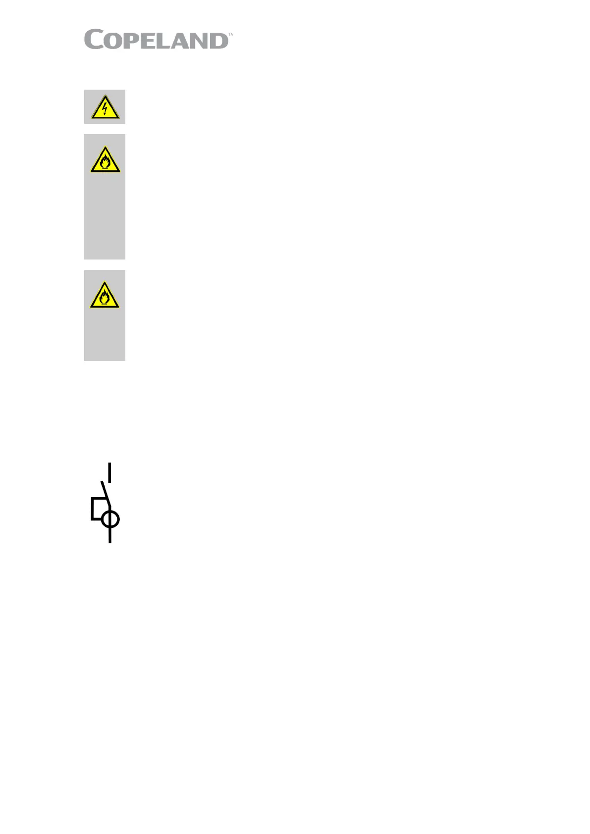
NOTE: It is recommended to install a residual current device (RCD) in any electrical system
associated with 2D*, 3D* and 8D* compressors and A2L flammable refrigerants such as
R454C, R455A and R454A. The purpose of the RCD is to detect current leaks to the ground in
case of electrical issues, for example with the terminal connection pins or electrical
accessories.
Figure 17: Residual current device (RCD)
The 2D*, 3D* and 8D* compressors are available in different three-phase motor versions. They all
can be started Direct-On-Line. In addition to the direct-online start, motor versions for part-winding
or star-delta start can be used.
The position of bridges required for Direct-On-Line start (depending on type of motor and/or mains
voltage) is shown in section 4.2.3 "Terminal box jumpers positionsTerminal box jumpers
position".
4.2.1 Part-winding motors (YY/Y) – Code A
Part-winding motors contain two separate windings (2/3 + 1/3) which are internally connected in star
and operated in parallel.
The first part-winding, ie, the 2/3 winding on terminals 1-2-3, can be used for part-winding start by
removing the bridges. After a time delay of 1 ± 0.1 seconds the second part-winding, ie, the 1/3
winding on terminals 7-8-9, must be brought on line.
4.2.2 Star / Delta motors (Y/∆) – Code E
This motor is interchangeable for star (Y) or delta (∆) operation by means of bridges. It is suitable for
two voltage ranges, eg, 220-240 V in delta, 380-420 V in star connection. If the supply voltage and
the nominal voltage of the motor in ∆-connection are identical, the star connection motor can also be
used for starting (remove bridges!).

 Loading...