AGL_HA_ST_Discus_A2L_A1_EN_Rev00 15
4 Electrical connection
4.1 General recommendations
The compressor terminal box has a wiring diagram on the inside of its cover. Before connecting the
compressor, ensure the supply voltage, the phases and the frequency match the nameplate data.
When the compressor is shipped the motor protector is mounted in the terminal box. The thermistors
are factory connected. The power supply and the control circuit must be wired according to the wiring
diagram on the inside of the terminal box cover. For more information on the wiring diagrams, please
also visit www.climate.emerson.com/en-gb.
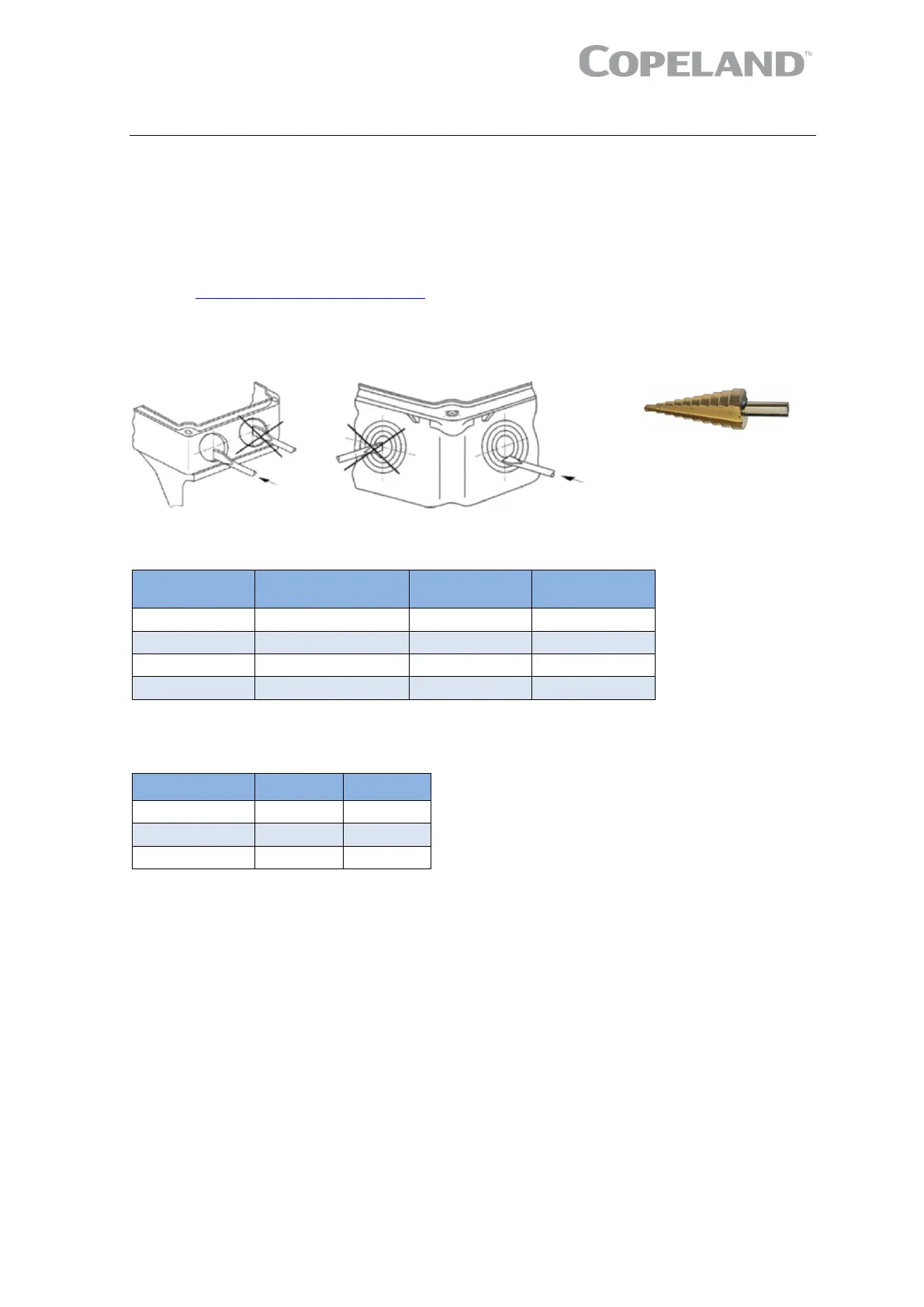
The knockouts on the terminal box have to be removed before the electrical glands can be installed.
First make sure that the terminal box is closed with its cover. Emerson recommends to use a subland
twist driller to avoid any damage to the box while removing the knockouts.
Figure 16: Terminal box preparation for cable gland fitting
Hole diameter
at terminal box (mm)
Table 4: Characteristics of the holes for cable bushings
The protection class of each terminal box according to IEC 60529 is given in Table 5 hereunder.
Also refer to Section 4.3 "Terminal box".
Models Class Option
Table 5: Protection class
For safety reasons, Emerson recommends that the electrical installation be executed in compliance
with standard EN 60204-1 and/or other standards and regulations of application when dealing with
A2L mildly flammable refrigerants such as R454C, R455A and R454A.
When installing 2D*, 3D* or 8D* compressors in A2L systems, the following measures must be taken:
To ensure the wires are properly terminated, the correct terminal and clamping tool for the
selected wire size must be used.
The ground wiring must conform to local regulations and codes of practice (only the provided
parts must be used).
The grounding screw must be torqued to 4.5 to 5.7 Nm.
A cable strain-relief device must be added.
Cable and wires must be protected against sharp edges.

 Loading...