18 AGL_HA_ST_Discus_A2L_A1_EN_Rev00
4.5 Compressor protection
All Copeland 2D*, 3D* and 8D* compressor models are factory-fitted with a compressor protection.
The letter "W" in the motor code of the 3-phase motors indicates a thermistor protection device. The
temperature-dependent resistance of the thermistor (PTC-resistance) is used to sense the winding
temperature. One chain of three thermistors (on 2D* and 3D* compressors) or two chains of three
thermistors (on 8D* compressors), each connected in series, are embedded in the motor windings
in such a manner that the temperature of the thermistors can follow with little inertia.
The 2D*, 3D* and 8D* compressors use the Kriwan modules INT69-2 and INT69TM-2, a new
generation of thermistor protection that has the same main features as the previous one (INT69 &
INT69TM). The motor protection module is connected to the thermistors in the terminal box. It
switches a control relay depending on the thermistor resistance:
INT69-2: one or two thermistor chains and 5-minute time delay
INT69TM-2: two thermistor chains
Caution: The maximum test voltage for thermistors is 3 V.
The total resistance of the thermistor chains on a cold compressor should be ≤ 1800 Ω.
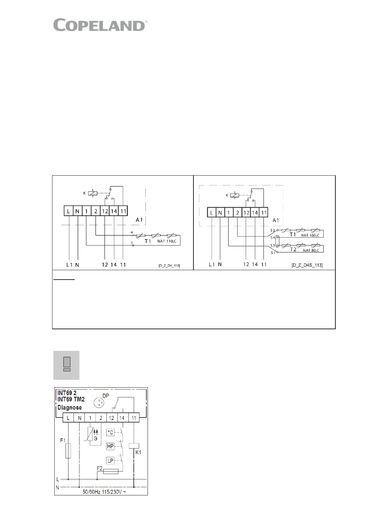
INT69-2 (2D*, 3D*) INT69TM-2 (8D*)
Legend
L ....... Voltage connection 3+4 ........ Cable bushings of thermistor connections
N ....... Neutral connection in terminal box
1+2 ... Thermistor chain connection S1-S4 .... Cable bushings of thermistor connections
12 ..... Alarm connection in terminal box (8D*)
14 ..... Control circuit T1+T2 .... Thermistor chain (about 90 Ω to 750 Ω per
11 ..... Control voltage connection chain at +20 °C)
A1 ..... Release module NAT ....... Nominal response temperature
Figure 20: Internal wiring
Protection class of the protection module: IP20.
Different sources for power supply and contact 11-
malfunction! Use the same potential for the power supply and the switch
contact of the control loop (11-14).
Figure 21: Control circuit wiring

 Loading...