22 AGL_HA_ST_Discus_A2L_A1_EN_Rev00
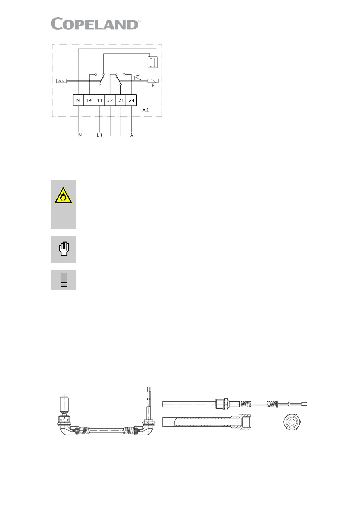
Legend:
11 = Voltage connection
21 = Control voltage connection
22 = Control circuit
24 = Alarm connection
A5 = Compressor terminal box
R = Relay
N = Neutral connection
t = Time delay
Figure 26: Wiring diagram FD-113ZU
Protection class: IP30.
4.8 Crankcase heaters
Ignition source in a potentially flammable atmosphere due to hot surface
temperature! Fire hazard! The crankcase heater is not an ignition source
during normal operation in an A2L-refrigerant system but could become one if
not installed properly according to installation instructions.
Ensure correct mechanical installation of the crankcase heater into the sleeve
or compressor housing. Use heat transfer paste for adequate heat transfer.
Overheating and burnout! Compressor damage! Never apply power to the
crankcase heater in free air, before the crankcase heater is installed on the
compressor or when it is not in complete contact with the compressor shell.
Oil dilution! Bearing malfunction! Turn the crankcase heater on 12 hours
before starting the compressor.
A crankcase heater is used to prevent refrigerant from migrating into the shell during standstill
periods.
The crankcase heater must remain energized during compressor off cycles. The initial start-up in the
field is a very critical period for any compressor because all load-bearing surfaces are new and
require a short break-in period to carry high loads under adverse conditions.
The crankcase heater must be turned on a minimum of 12 hours prior to starting the compressor.
This will prevent oil dilution and bearing stress on initial start-up.
4.8.1 70-Watt and 100-Watt heater element
The 70-Watt heater for 2D* compressors is screwed into a pocket.
Heaters for 3D* compressors are screwed into a sleeve – see Figure 27.
Figure 27: 70-Watt & 100-Watt crankcase heater elements

 Loading...