EasyManuals Logo
Home>Emerson>Controller>E2

Emerson E2 User Manual

Emerson E2
283 pages
To Next Page IconTo Next Page
To Previous Page IconTo Previous Page
Page #73 background imageLoading...
Page #73 background image
0v SIG
INPUT 1
0v SIG
INPUT 11
0v SIG
INPUT 10
0v SIG
INPUT 12
0v SIG
INPUT 13
0v SIG
INPUT 2
0v SIG
INPUT 15
0v SIG
INPUT 16
0v SIG
INPUT 14
0v SIG
INPUT 3
0v SIG
INPUT 4
0v SIG
INPUT 7
0v SIG
INPUT 5
0v SIG
INPUT 6
0v SIG
INPUT 9
0v SIG
INPUT 8
S2
2345678
1
ON
S1
23456 78
1
ON
S4
2345678
1
ON
S3
2345678
1
ON
+
1
2
V
+
5
V
+
5
V
+
5
V
MULTIFLEX BOARD
MULTIFLEX COMBINATION I/O BOARD
INSTALLATION GUIDE
7
1.
2. Set the network address on the first five rockers of dip switch
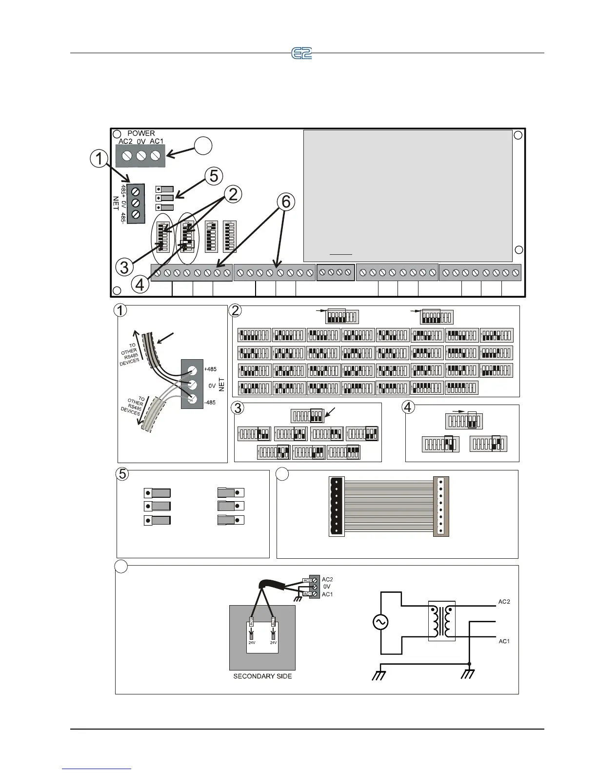
S3 for the 16AI, and S4 for the 8RO sections of the MultiFlex.
3. Set the network address on rockers 6-8 on S4 for the
4AO or 8DO sections of the MultiFlex if applicable (88AO
and 168AO have a 4AO section). The 168DO has an
8DO section.
4. Set the network baud rate using rockers 6 and 7 of dip
switch S3. For 9600 baud, set #6 UP and #7 DOWN.
For 19200 baud, set #6 DOWN and #7 UP.
5. Set RS485 termination jumpers OUT (term) if at either end
of a daisy chain. Otherwise, set jumpers IN (no term).
6.
Connect board to the RS485 I/O Network.
If replacing an old 8IO or 16AI, use MultiFlex input
adapters (P/N 335-2301) to plug input connectors from old board
into the MultiFlex input sockets. One for inputs 1-4,
and one for inputs 5-8. Otherwise, polarity-sensitive inputs
will have to be rewired. (No adapter is needed for inputs 9-16.)
7. Connect board to power transformer.
If a center tap is
present, use the center tap! Instead, connect 0V
terminal to a separate Earth ground.
DO NOT
NO TERMINATION
TERMINATION
OUT
IN
J
P2
J
P4
J
P3
J
P2
J
P4
JP3
PLUG INPUT
CONNECTOR
FROM 16AI
INTO THIS
END
#1
#2
#3
#4
#4
#3
#2
#1
PLUG CABLE
CONNECTOR
INTO
MULTIFLEX 16
INPUT SOCKET
MULTIFLEX INPUT ADAPTER
P/N 335-2301
6
YELLOW
YELLOW
0V
24 VAC
24 VAC
120/208/240 VAC
•
P/N 640-0041, 120VAC Primary,
50VA
•
P/N 640-0050, 120VAC Primary,
75VA
•
P/N 640-0042, 220VAC Primary,
50VA
•
P/N 640-0056, Multi-tap
120/208/240VAC Primary, 56VA
•
P/N 640-0080, Multi-tap
120/208/240VAC Primary, 80VA
Note: Please refer to transformer
for primary side wiring.
Acceptable CPC Transformers:
2
3
4
5
6
7
8
1
ON
2
3
4
5
6
7
8
1
ON
2
3
4
5
6
7
8
1
ON
2
3
4
5
6
7
8
1
ON
2345678
1
ON
23456 78
1
ON
2
3
4
5
6
7
8
1
ON
2345678
1
ON
2
3
4
5
6
7
8
1
ON
2
3
4
5
6
7
8
1
ON
2
3
4
5
6
7
8
1
ON
2
3
4
5
6
7
8
1
ON
2345678
1
ON
2345678
1
ON
2
3
4
5
6
7
8
1
ON
2345678
1
ON
BOARD 1
BOARD 2
BOARD 3
BOARD 4
BOARD 5
BOARD 6
BOARD 7
BOARD 8
BOARD 9
BOARD 10
BOARD 11
BOARD 12
BOARD 13
BOARD 14
BOARD 15
BOARD 16
2345678
1
ON
23456 78
1
ON
2
3
4
5
6
7
8
1
ON
2345678
1
ON
BOARD 17 BOARD 18
BOARD 19
BOARD 20
23456
7
8
1
S3: INPUT (16AI)
ADDRESS
2
3
4
5
6
7
8
1
S4: RELAY (8RO)
ADDRESS
2
3
4
5
6
7
8
1
ON
2
3
4
5
6
7
8
1
ON
2
3
4
5
6
7
8
1
ON
BOARD 21
BOARD 22
BOARD 23
2
3
4
5
6
7
8
1
ON
2345678
1
ON
2345678
1
ON
2
3
4
5
6
7
8
1
ON
2345678
1
ON
2
3
4
5
6
7
8
1
ON
BOARD 24
BOARD 25 BOARD 26
BOARD 27
BOARD 28
BOARD 29
2
3
4
5
6
7
8
1
ON
2
3
4
5
6
7
8
1
ON
BOARD 30
BOARD 31
2
3
4
5
6
7
8
1
S3: BAUD RATE
2
3
4
5
6
7
8
1
2
3
4
5
6
7
8
1
19200 BAUD
9600 BAUD
2345678
1
2345678
1
ON
2345678
1
ON
2345678
1
ON
BOARD 1 BOARD 2 BOARD 3
2345678
1
ON
2345678
1
ON
2
3
4
5
6
7
8
1
ON
BOARD 4
BOARD 5 BOARD 6
2345
6
7
8
1
ON
BOARD 7
S4: ANALOG (4AO) ADDRESS
(or 8DO ADDRESS OF THE
168DO BOARD)
SHIELDED TWISTED PAIR
BELDEN #8761. FOR PLENUM,
USE BELDEN #82761 OR #88761
OR EQUIV.
WIRE + to + (same color)
WIRE 0V to 0V
WIRE - to - (same color)
7
BACnet The RS485 Network and Hardware Setup • 6-17

Table of Contents

Other manuals for Emerson E2

Questions and Answers:

Question and Answer IconNeed help?

Do you have a question about the Emerson E2 and is the answer not in the manual?

Emerson E2 Specifications

General IconGeneral
BrandEmerson
ModelE2
CategoryController
LanguageEnglish

Related product manuals