Figure 9-2 - Input Type Dip Switches for MultiFlex 16 and 16AI
Boards
26501070
2
2
3
3
4
4
5
5
6
6
7
7
8
8
1
1
ON
ON
S1
S2
INPUTS 9-16
INPUTS 1-8
Set DOWN for
sensors requiring
voltage
Set UP for
sensors not requiring
voltage
9-2 • E2 RX/BX/CX I&O Manual 026-1614 Rev 4 5-JAN-2013
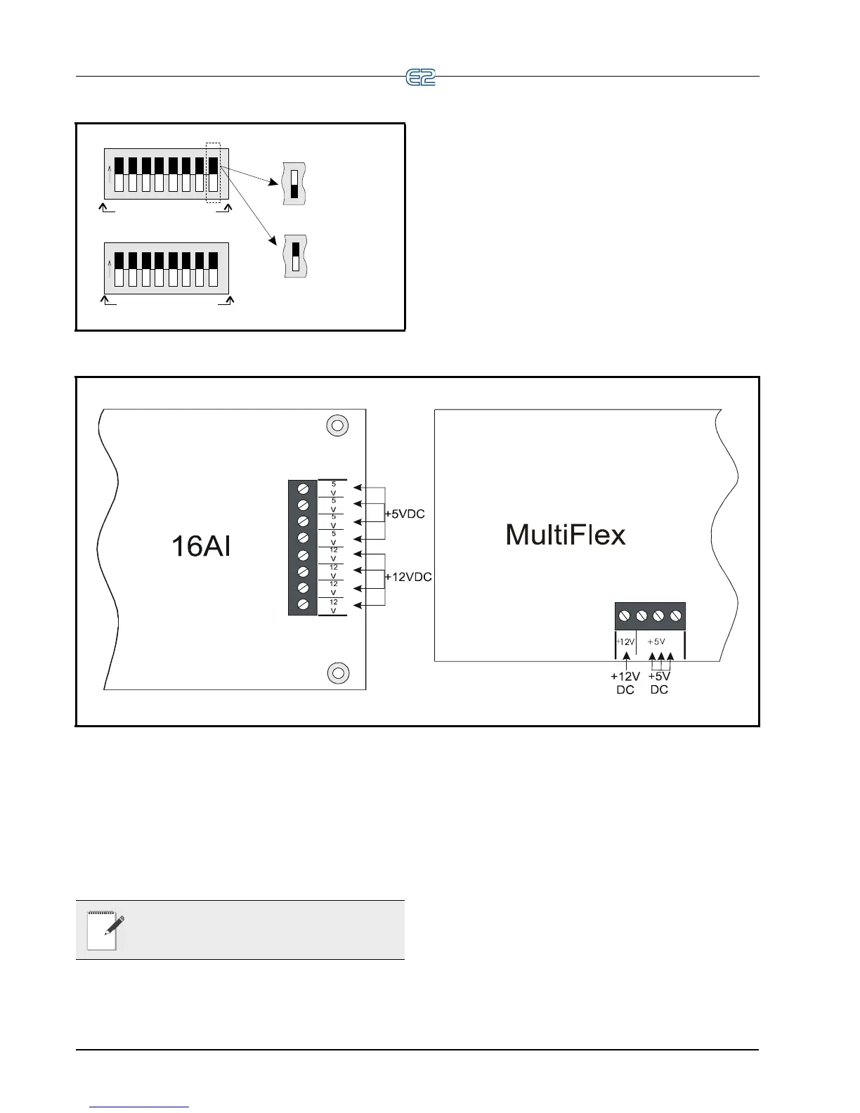
9.1.2 Power Connection
If power is needed to operate the sensor, several termi-
nals exist on the 16AI, Multiflex boards, 8IO, that may be
used to
supply DC power (see Figure 9-3 for 16AI and
MultiFlex power connections).
Figure 9-3 - Input Board Power Sources
Input boards may supply 12VDC or 5VDC. To connect
to one of the DC power sources, simply connect the sen-
sor’s power wire to one of the terminals.
The maximum current that may be drawn from the
+12V
DC terminal is 100 milliamps. The maximum cur-
rent that can be drawn from all three +5VDC terminals
COMBINED is 50 mi
lliamps.
NOTE: For 24VAC sensors, a separate trans-
former must be used unles
s specified other-
wise in Table 9-1 on page 9-3.
Specific wiring instructions
for each type of sensor are
given in Table 9-1 on page 9-3.

 Loading...