Micro Motion
®
Model D and DT Sensors Instruction Manual 21
Wiring continued
Model DT sensor cable
Connecting and shielding 9-wire
cable
A 9-wire connection is required between the junction box and the core
processor or transmitter. Micro Motion offers two types of 9-wire cable:
• Shielded
•Armored
Both cable types contain shield drain wires. You may also use jacketed
cable with conduit.
Cable connections to sensor and transmitter
The wiring procedure is the same for the sensor and transmitter. Refer to
the wiring diagrams on the following pages, and follow these steps:
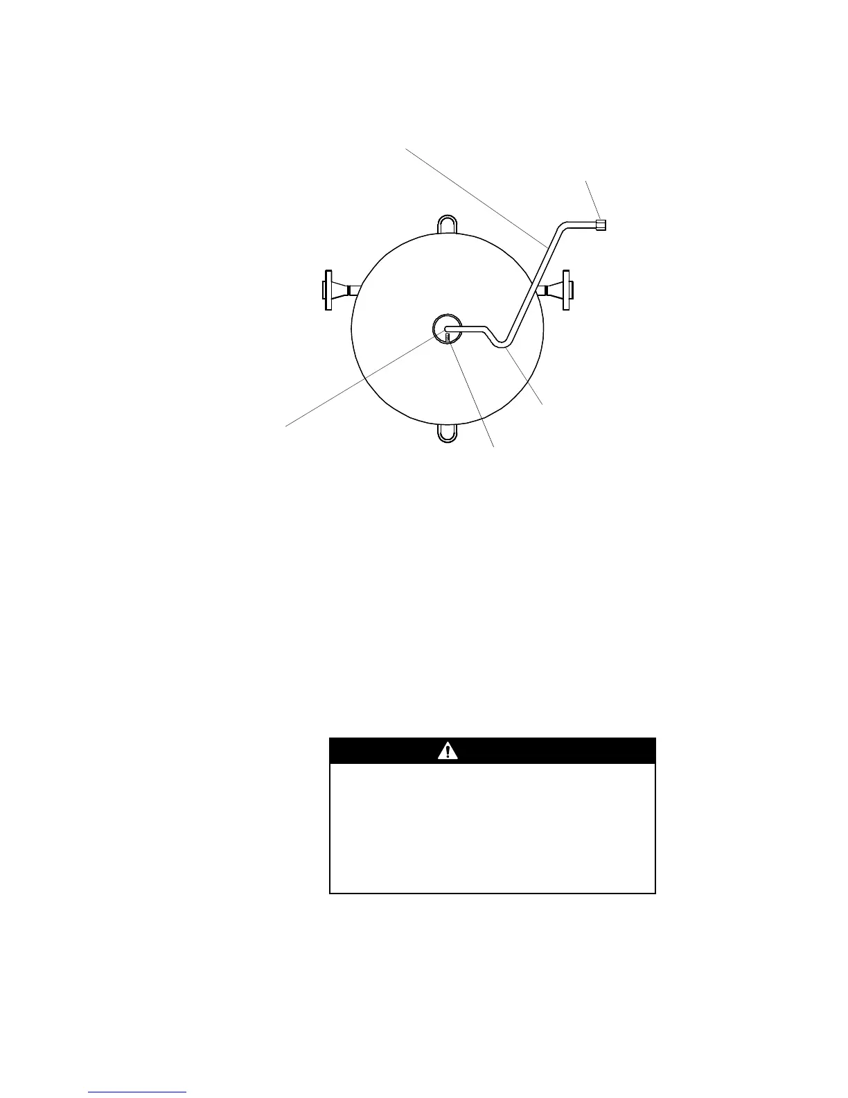
Drip leg
1/2" NPT
conduit fitting
3 ft. (1 m) factory-supplied flex conduit
• Liquid tight to meet CE requirements
for European installations
• Permanently attached to sensor
Grounding screw
1/2" NPT conduit fitting
• Factory-supplied fitting
• Ensure 360
° contact
Failure to seal the sensor and transmitter housings
could cause a short circuit, which would result in
measurement error or flowmeter failure.
• Ensure integrity of gaskets and O-rings.
• Grease all O-rings before sealing.
• Install drip legs in cable or conduit.
• Seal all conduit openings.

 Loading...