Micro Motion
®
Model D and DT Sensors Instruction Manual 29
Wiring continued
Remote booster amplifier drive wiring
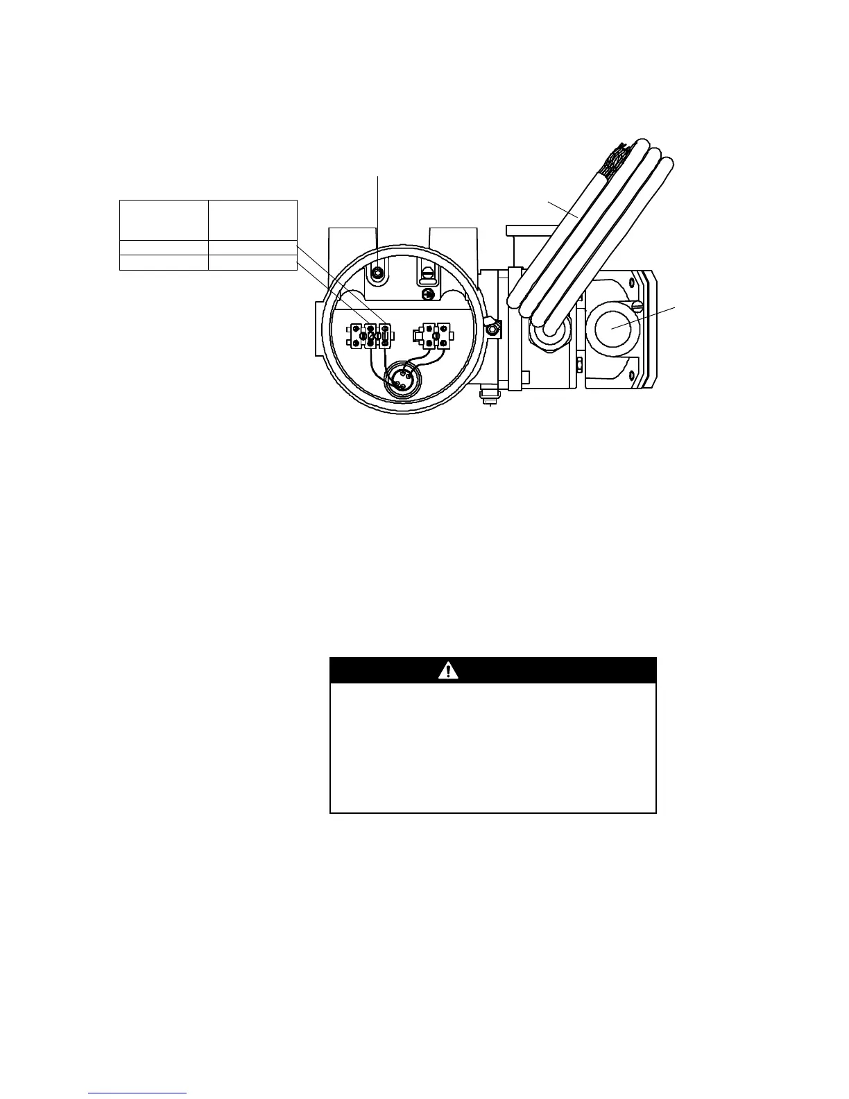
Wiring to a transmitter (D600
sensor with junction box)
The instructions in this section explain how to connect a fully prepared
9-wire Micro Motion flowmeter cable to the sensor and transmitter.
• The procedure for preparing Micro Motion cable and cable glands is
described in the instructions that are shipped with the cable.
• Install cable and wiring to meet local code requirements.
Cable connections to sensor and transmitter
The wiring procedure is the same for the sensor and transmitter. Refer to
the wiring diagrams on the following pages, and follow these steps:
Failure to seal the sensor and transmitter housings
could cause a short circuit, which would result in
measurement error or flowmeter failure.
• Ensure integrity of gaskets and O-rings.
• Grease all O-rings before sealing.
• Install drip legs in cable or conduit.
• Seal all conduit openings.

 Loading...