28 Micro Motion
®
Model D and DT Sensors Instruction Manual
Wiring continued
Wiring from the remote booster
amplifier to the sensor
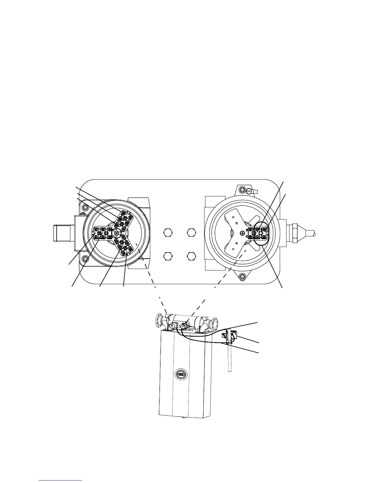
For intrinsically safe junction box wiring (see left side of figure below):
• Terminate factory-supplied 9-wire cable. Match wire colors to the
corresponding terminal wire colors from the remote booster amplifier.
• Orange wire in cable does not have corresponding orange wire from
sensor. Note: Terminate the orange wire in cable to the terminal shown
in diagram below.
• Clip remaining wires (brown and red) of cable (intrinsically safe side
only) and insulate.
For explosion-proof junction box wiring (see right side of figure below):
Install user-supplied drive wiring, shielded 18 AWG (0,75 mm
2
) 2-wire
cable, from remote booster amplifier terminals 1 and 2 to sensor
terminals 1 and 2. (See figure on page 29 for wiring at booster amplifier.)
Remote booster amplifier wiring to sensor
User-supplied drive wiring,
18 AWG (0,75 mm
2
). See
page 29 for connections at
remote booster amplifier.
White
Blue
Violet
Ye l l o w
Orange
Red (factory wired)
Brown (factory wired)
Factory-supplied drive
wiring
Gray
Factory-supplied 9-wire
cable for intrinsically safe
wiring (RTD and pickoffs)
Remote booster amplifier
Green
Explosion-proof wiringIntrinsically safe wiring
12

 Loading...