EasyManuals Logo
Home>Emerson>Measuring Instruments>Micro Motion

Emerson Micro Motion Installation Manual

Emerson Micro Motion
74 pages
To Next Page IconTo Next Page
To Previous Page IconTo Previous Page
Page #30 background imageLoading...
Page #30 background image
26 Micro Motion
®
Model D and DT Sensors Instruction Manual
Wiring continued
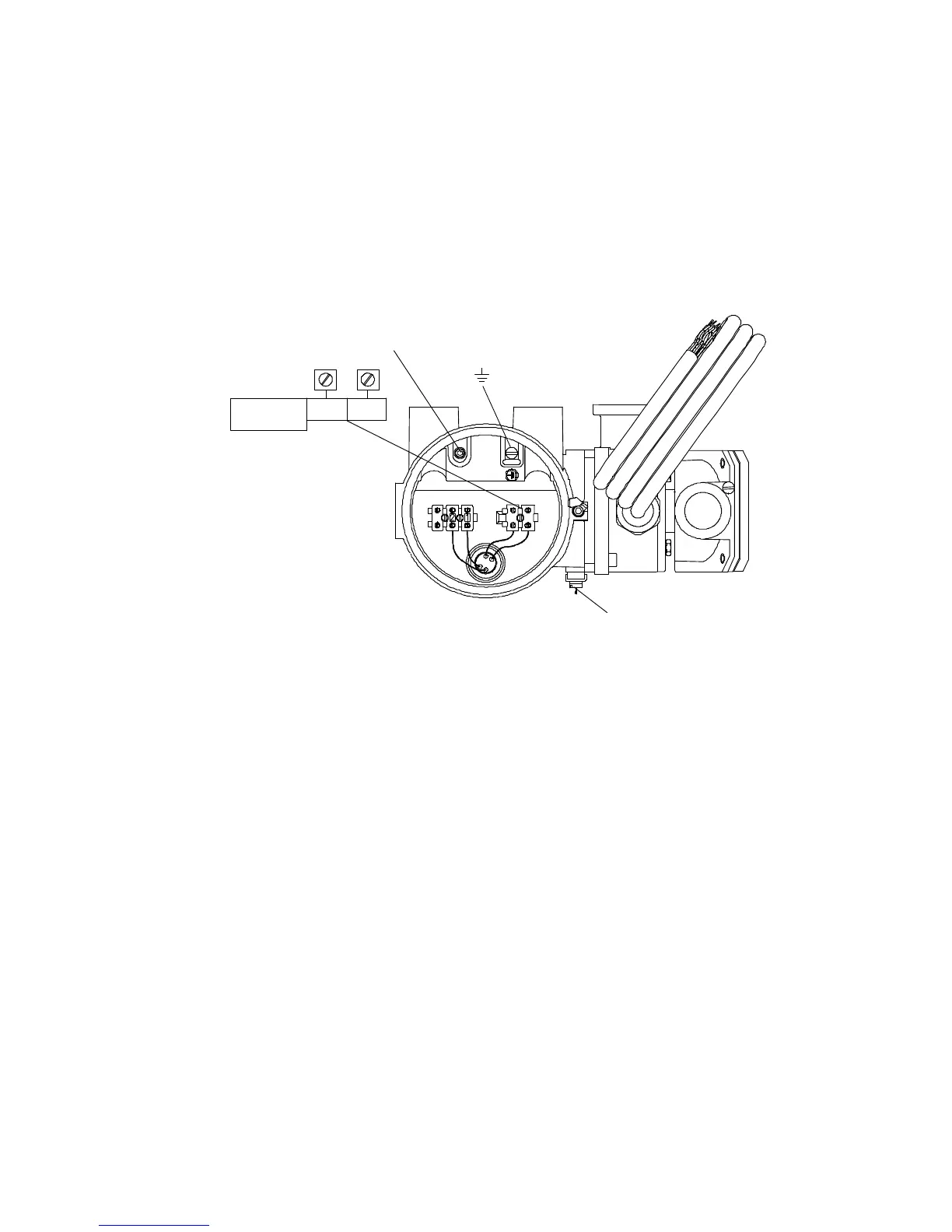
Power supply wiring to the
remote booster amplifier
Remove screw and terminal cover before installing wiring. Re-install
cover before operating.
Provide 85-250 VAC power to terminals L2 and L1 as shown in the
diagram below.
This unit is provided with an external terminal for supplementary
bonding connections. This terminal is for use where local codes or
authorities permit or require such connections.
Remote booster amplifier power-supply wiring
Screw and terminal cover
Chassis ground
L/L
1
N/L
2
85-250 VAC
50/60 Hz
Supplementary bonding connection

Other manuals for Emerson Micro Motion

Questions and Answers:

Question and Answer IconNeed help?

Do you have a question about the Emerson Micro Motion and is the answer not in the manual?

Emerson Micro Motion Specifications

General IconGeneral
BrandEmerson
ModelMicro Motion
CategoryMeasuring Instruments
LanguageEnglish

Related product manuals