EasyManuals Logo
Home>Emerson>Measuring Instruments>RLDS

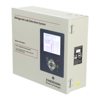
Emerson RLDS User Manual

Emerson RLDS
82 pages
To Next Page IconTo Next Page
To Previous Page IconTo Previous Page
Page #18 background imageLoading...
Page #18 background image
10 • RLDS I&O Manual 026-1309 Rev 8
3.5. RLDS Interior
Figure 3-7 - Diagram of RLDS Interior
Universal
Power Supply
Intake
Manifold
Solenoid
Connectors
Dual 4-20 mA
Outputs (Signal
Out Only)
Screw Terminal
Microcontroller
Board
Intake
Manifold
Solenoids
AC Input
Terminals
IR Bench
Gas Out
Gas Sample
Pump
AC Input
Ground Stud
Main
Board
IR Bench
Gas In
AC Input
Ground
Stud
Hydrophobic
Filter
Dual 4-20 mA
Outputs Option
Card Socket
Figure 3-8 - RLDS Processor Board Layout
Microcontroller
Board
RLDS
Main Circuit
Board
Terminator
Switch
Relay Connector
Alarm 1,2,3 Fault
Factory
Default
RS485
Connector
4-20 mA Output Only
(DO NOT APPLY POWER)
CPU
Reset
Figure 3-9 - Relay, RS485, and AC Input Connections
Relay Connectors:
Leak, Spill, Evacuate,
Fault
RS485
Connector
AC Input
Terminals

Table of Contents

Questions and Answers:

Question and Answer IconNeed help?

Do you have a question about the Emerson RLDS and is the answer not in the manual?

Emerson RLDS Specifications

General IconGeneral
BrandEmerson
ModelRLDS
CategoryMeasuring Instruments
LanguageEnglish

Related product manuals