The Diagnostic Screen General Operation of RLDS - UI • 41
8.10. The Diagnostic Screen
8.10.1. Navigating to the Diagnostic Screen
On the System Setup screen (Figure 7-3), select the
Diagnostic option (DIAG).
Diagnostic Screen
Diagnostic Options and Controls
8.10.2. Diagnostic Screen Overview
The Diagnostic Screen contains sensor data and status
information useful for trouble shooting various fault
conditions. An explanation of each line is given
below along with normal operating ranges.
DET: Detector Voltage - Peak-to-peak output of the
IR sensor, in the absence of gas this value can range
from 3.900V to 4.500V.
AVE: Average Detector Voltage - Running
average of the values displayed in line 1 (DET).
ZERO: Zero Voltage - IR sensor output that was
stored during the last purge cycle and has the same
range as line 1 (DET).
NOISE: A 16-point running average of the noise
portion of IR bench output. This reading is valuable
mainly when refrigerant is not
present.
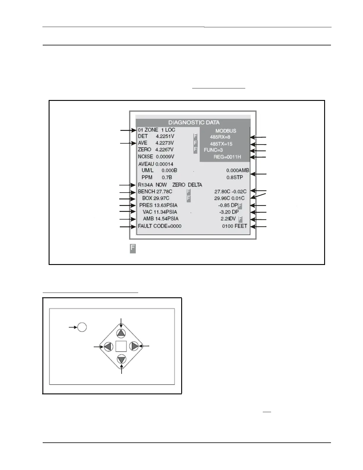
Figure 8-12 - Diagnostic Screen Layout
Current active
zone &
programmed name
Optical Sensor
Output Voltages
Optical Sensor
Output Voltages
Programmed gas
type for active zone
Chassis Temperature
Vacuum Pressure
Optical Bench Temperature
Ambient Pressure
Manifold Pressure
Hexidecimal Fault
Code
Indicates parameter is out of
tolerance & causing a fault condition
Register address
Temps at last purge
& difference from
current temps
Transmit port #bytes
Modbus function
Absorbance &
concentration data
Manifold - ambient
Receive port #bytes
Vacuum - ambient
Programmed length
of tubing for active
zone
Figure 8-13 - Diagnostic Options and Controls
SILENCE
ESC
Quit; go
back to
menu
Clears Modbus Data
Forces a
purge cycle
Pump ON/OFF Control
Navigates to
the next zone

 Loading...