E2, Einstein, and REFLECS Controllers (The RLDS Gateway Board) Connecting Communication Devices • 17
4.2.2. Gateway Board Networking
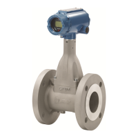
To connect the Gateway to an RLDS, punch out one
of the remaining service knockouts to gain access to
the interior of the RLDS monitor. Locate the RS485
connector and remove it from the circuit board.
Secure the wire leads to the connector orienting them
as shown in Figure 4-8. When you are through secur-
ing the connections, carefully plug the connector back
onto the circuit board.
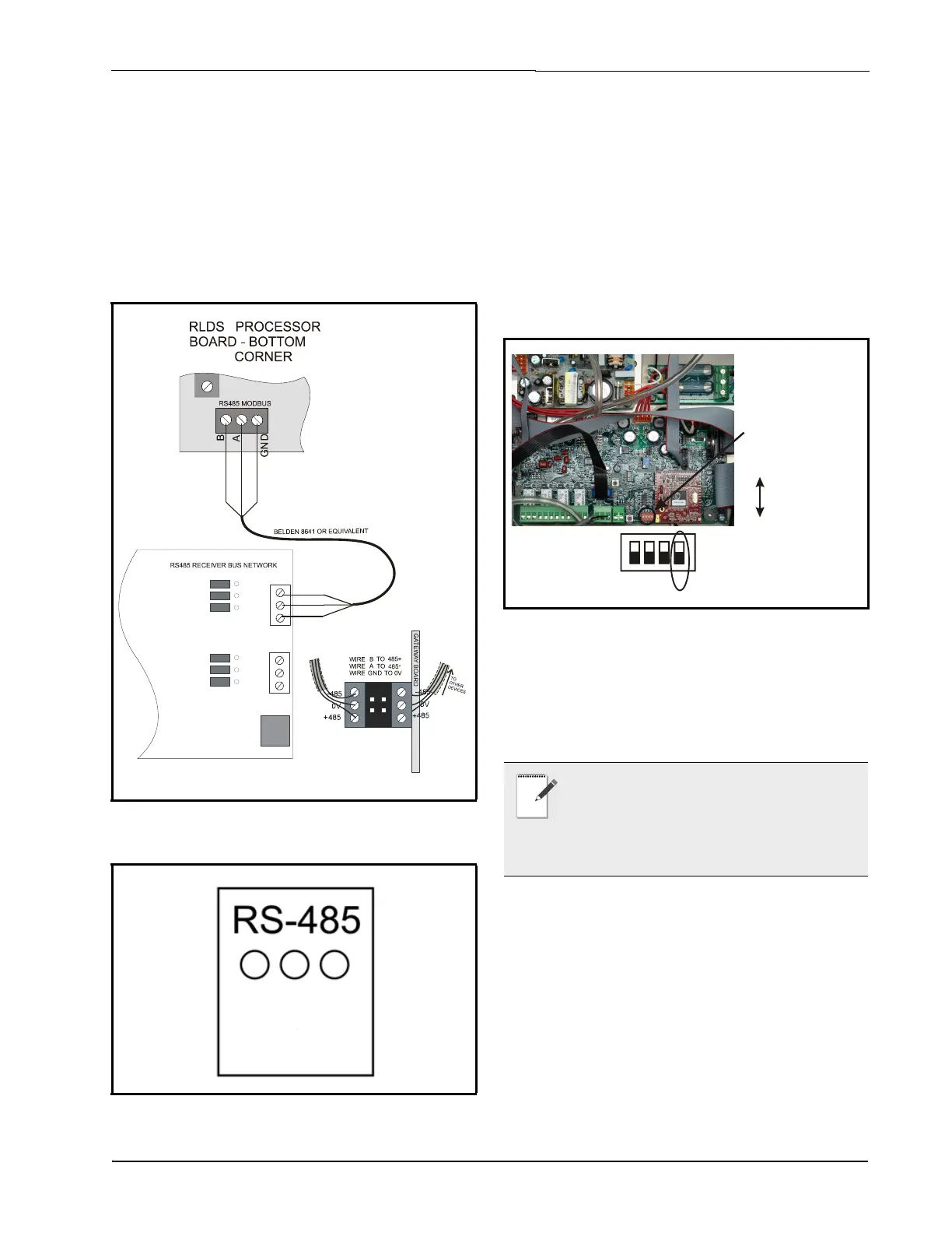
4.2.2.1. Changing Terminator Switch
Settings
The terminator switch is shipped from the factory in
the terminated or DOWN position. This is the
correct setting if the RLDS is connected to a single
device, or it is the last device on the network chain. If
the RLDS is to be installed in the middle of a network,
the terminator must be moved to the UP position.
Locate switch 4 and determine its position. If it needs
to be moved, slide the switch to the appropriate
position.
4.2.2.2. RLDS Node Address
The node address is set through the front display of
the RLDS unit. Refer to Section 7.16., Node Address
for more information.
Figure 4-8 - RLDS and Gateway Board Wiring
Figure 4-9 - RS485 Connector - RLDS
LEFT
R
S
4
8
5
+
R
S
4
8
5
-
0
v
Gateway Board
RS485 -
RS485 +
GND
Side view of
double-stack
Modbus
connector
on Gateway
0v
I/O Net
M
O
D
B
U
S
C
O
N
N
E
C
T
O
R
Figure 4-10 - Positioning the Termination Switch - RLDS
NOTE: If connecting RLDS units to an
Emerson Electronics and Solutions site
controller network, you MUST number the
units from 1-3. The Gateway Board will not
recognize any RLDS unit with a number that is not 1, 2,
or 3.
DOWN (Terminated)
1
4
23
Termination
is set using
switch 4 (SM1)

 Loading...