Overview
1-2 Introduction
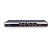
Figure 1-1 A4H124-24FX Front Panel
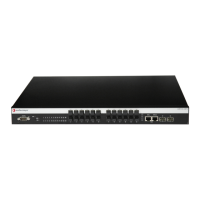
Figure 1-2 A4H254-8F8T Front Panel
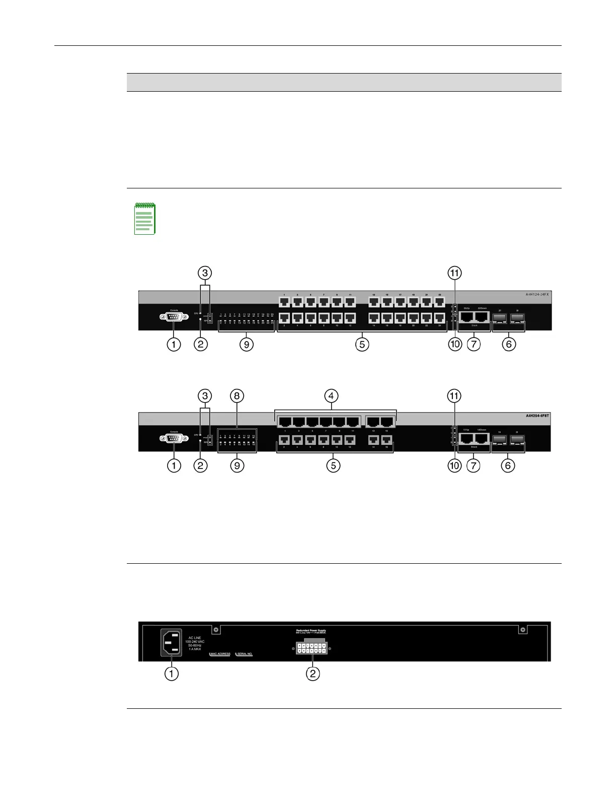
Figure 1-3 shows the back panel of the A4 switches.
Figure 1-3 A4 Switch Back Panel
A4H254-8F8T
(see Figure 1-2 on page 1-2)
• Eight 10/100Base-T ports (labeled odd numbers 1 – 15)
• Eight 100Base-FX MT-RJ ports (labeled even numbers 2
– 16)
• Two 10/100/1000Base-T RJ45 ports which can be used
as stacking ports or as Ethernet uplink ports (labeled 17
and 18)
• Two Gigabit Ethernet SFP ports (labeled 19 and 20)
Notes: Each SFP port supports the installation of 1000BASE-SX, 1000BASE-LX, or 1000BASE-T
SFP pluggable transceivers.
1 Console port 7 RJ45 10/100/1000 stack/uplink ports
2 Password reset button 8 RJ45 port status LEDs
3 Switch status LEDs 9 MT-RJ port status LEDs
4 RJ45 10/100 Mbps ports 10 SFP port status LEDs
5 MT-RJ fiber optic ports 11 RJ45 stack/uplink port status LEDs
6 SFP slots
1 AC power input connector 2 Redundant power supply connector
Table 1-1 A4 Switch Port Types (continued)
A4 Model Ports
 Loading...