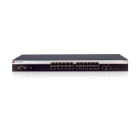
Checking the LEDs
Enterasys A4 Fast Ethernet Switch Hardware Installation Guide 3-3
RPS LED
The RPS LED indicates the state of the internal power supply and whether a redundant power
supply is providing power, as described in Table 3-2.
UP LED
The STACK UP LED indicates the state of the connection to the switch stack down connector, as
described in Table 3-3.
Table 3-2 RPS LED Definitions
Color State Recommended Action
Off Connected RPS not in use. None.
Internal power supply failed. If an RPS is connected to the switch, it
should be providing power. Perform the
following:
1. Ensure the RPS is powered on.
2. Ensure that the AC power cord to the RPS
is plugged in correctly and that there is
power at the AC power source.
3. Replace the power cord with a known
good one.
4. Ensure the DC power cord from the RPS
to the switch is plugged in correctly.
5. If the problem persists, contact
Enterasys Networks for technical support.
Amber Solid. The switch internal power supply
failed, and the RPS is providing the proper
power to the switch.
Perform the following:
1. Ensure that the AC power cord to the
switch is plugged in correctly and that
there is power at the AC power source.
2. Replace the power cord with a known
good one.
3. If the problem persists, contact
Enterasys Networks for technical support.
Table 3-3 UP LED Definitions
Color State Recommended Action
Off No valid connection to switch stack down
connector.
1. Make sure the switch connected to the
stack down connector is powered on.
2. Replace cable with a known good one.
3. If the problem still exists, contact
Enterasys Networks for technical support.
Green Solid. Valid connection to switch stack
down connector.
None.
Blinking. Information is being transferred
through the stacking cable.
None.
 Loading...